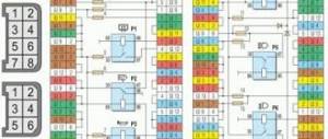
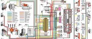
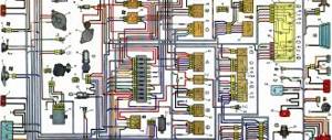
Electrical diagram of the car IZH 2126
Color diagrams with electrical equipment of the domestic passenger car IZH 2126 “Oda”. The wiring of IZH 2126 is made according to a single-wire circuit: the negative terminals of sources and consumers of electricity are connected to ground. When the engine is not running, all consumers are powered by the battery, and after the engine is started - by an alternating current generator with a built-in rectifier and electronic voltage regulator. When the generator is running, the battery is charged. The main electrical circuits are protected by fuses installed in the mounting block. The fuse rating and the circuit it protects can be determined from the tables (for old and new mounting blocks). The electric motor of the windshield wiper gearmotor is protected by an automatic reusable bimetallic fuse. There are no fuses in the ignition, starter, or battery charge circuits.List of fuses IZH 2126 “Oda”
Both old and new (with knife-type fuses) blocks can be installed on the car. Blocks of different designs are not interchangeable.
Fuse number (current, A) Electrical circuits protected by fuses
1(8) Reserve
2(8) Reserve
3(8) Reserve
4(16) Radiator fan relay coil. Electrical circuit of switches and electric motor of the heater
5(3) Hazard light switch (in turn signal mode), turn signal switch, turn signal switch Turn signal warning light, turn signal warning lights Reversing light switch, reversing lamps Tachometer Voltmeter Fuel gauge, fuel level sensor, warning light fuel level temperature gauge! coolant Temperature sensor Control lamp and emergency oil pressure sensor Brake system emergency lamp Hydraulic brake switch Parking brake switch
6(8) Brake light switch and lamps Interior lighting
7(8) Lamps for license plate lighting Control pump for turning on side lighting Lamps for illuminating the heater and cigarette lighter levers Glove box lighting Switch and lamps for instrument cluster lighting
8(16) Horn, horn switch Radiator fan motor
9(8) Side light bulb for left headlight Side light bulb for left rear light
10(8) Side light bulb for the right headlight Side light bulb for the right rear light bulb Switch for the fog light bulbs Indicator light for the fog lights
11 (8) Switch, turn signal breaker and turn signal lamps, control pump in hazard warning mode
12(16) Cigarette lighter, socket for portable lamp
13 (8) High beam right headlight
14 (8) Left high beam, high beam warning lamp
15(8) Low beam right headlight
16(8) Low beam left headlight
Electrical circuits protected by fuses (new type mounting block)
Fuse number (current type. A) Electrical circuits protected by fuses
F1(10 A) Reserve
F2(10A) Direction indicators and hazard warning relay (in hazard mode) Hazard warning lamp
F3(10A) Rear lights (brake lamps) Interior lamp
F4(20A) Rear window heating element Relay (contacts) for turning on the rear window heating Cigarette lighter, socket for a portable lamp
F5(20A) Horn, horn switch
F6(30A) Reserve
F7(30A) Heater fan electric motor Windshield washer motor Relay (winding) for turning on the electric radiator fan Relay (winding) turning on the heated rear window Indicator lamp for turning on the heated rear window Glove box lighting
F8(7.5 A) Reserve
F9(7.5 A) Reserve
F10(7.5 A) Left headlight (side light)
F11(7.5 A) Right headlight (side light)
F12(7.5 A) Right headlight (low beam)
F13(7.5 A) Left headlight (low beam)
F14 (7.5 A) Left headlight (high beam) Indicator lamp for turning on the high beam headlights
F15(7.5 A) Right headlight (high beam)
F16 (15 A) Direction indicators and hazard warning relay (in turn signal mode) Turn signal indicator lamp Rear lights (reversing lamps) Motor gearbox and windshield wiper activation relay Oil pressure indicator lamp Parking brake indicator lamp Coolant temperature gauge Fuel level gauge with reserve indicator lamp Voltmeter
Electrical diagram of the IZH-2126 car (click to enlarge)
Voltage is supplied to the corresponding lamp filaments through relays installed in the mounting block. External lighting modes are selected by the external lighting switch located on the instrument panel console. In the first position of the switch, the exterior lighting is turned off (in this case, the symbol on the switch key is constantly illuminated when the ignition is on). When you press the switch key to the second position, the side light lamps and instrument panel lighting are turned on. To turn on the low beam, press the button all the way, moving it to the third position. In this position of the key, you can turn on the high beam by pressing the left lever of the steering column switch away from you, as well as the rear fog lights - with the button located on the instrument panel trim to the left of the steering wheel. When the fog lights are turned on, the orange warning lamp located in the warning lamp block to the right of the steering wheel will light up.
Supply system
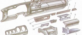
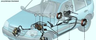
1 — fine fuel filter; 2 - fuel pump; 3 — air filter housing; 4 - carburetor; 5 — heated air supply hose; 6 — heated air intake; 7 - fuel line; 8 — fuel receiver; 9 — fuel tank plug; 10 - filling pipe; 11 — ventilation tube of the fuel tank; 12 — filling pipe coupling; 13 - fuel tank.
The power system contains a fuel tank, a fuel line, a fuel pump, fuel hoses, an air filter, a fine fuel filter, a carburetor, and cable drives for controlling the carburetor's throttle and air valves. The fuel tank is steel (45 l), located under the floor of the body in the rear seat area on the left and attached to the underbody in the rear with an anchor bolt, and in the front with two bolts. In the rear upper part of the fuel tank there are: a filler pipe, a ventilation pipe and a hole for installing a fuel receiver combined with a fuel level indicator sensor. A strainer is installed on the fuel inlet pipe in the fuel tank.
The ventilation hose is routed to the fuel filler neck on the left side of the body. The fuel line is steel, connected to the fuel tank and fuel pump through gasoline-resistant rubber-fabric hoses secured with clamps. The same hoses connect the fuel pump to the carburetor and fine fuel filter.
The fuel pump is diaphragm, mechanically driven by an eccentric on the camshaft (UMPO-331 engine) or on the drive shaft of auxiliary units (VAZ-2106 engine). The fuel pump is attached through a heat-insulating spacer and sealing gaskets to the head (UMPO-331 engine) or cylinder block. Despite their external similarity and similar design, fuel pumps are not interchangeable. The maximum pressure developed by the pump is 0.22–0.30 bar, productivity at a crankshaft speed of 3600 min-1 is 80 l/h (UMPO-331 engine) or 60 l/h (VAZ-2106 engine). The maximum pressure is determined by the stiffness of the pump spring (in the absence of diaphragm ruptures and valve leaks), and the pump performance depends on the protrusion of the pusher above the mating plane of the heat-insulating spacer; it is adjusted when installing the pump by selecting the thickness of the gaskets. The pump is equipped with a lever for manually pumping fuel, the need for which arises after the car has been parked for a long time (especially in hot weather), disassembling the fuel pump or carburetor, disconnecting the fuel hoses, or completely running out of fuel from the tank. The pump also has a fuel separator filter. The filter mesh element is washed in gasoline after removing the pump cover.
The fine fuel filter on the UMPO-331 engine is located between the fuel pump and the carburetor. As a rule, a fine fuel filter is not installed on a factory-built engine. Car owners are recommended to install it also in the area from the fuel pump to the carburetor and - attention! - arrow in the direction of the carburetor. The fine fuel filter is of a non-separable design and must be replaced if dirty or damaged. The service life of the filter is, as a rule, about 10 thousand km.
The air filter housing on both engines is mounted on top of the carburetor. To ensure the optimal composition of the combustible mixture, the temperature of the air entering the carburetor must be maintained within 25-35 ° C; For this purpose, air is taken both directly from the engine compartment and from the exhaust manifold, which quickly heats up to a high temperature after starting the engine. Therefore, in cold weather, the air filter housing pipe should be connected to the hot air intake pipe of the exhaust manifold with a special corrugated hose.
The air filter filter element is made of paper, non-separable design. The frequency of replacement of the replacement element is every 15 thousand km. When driving on heavily polluted roads (dirt roads or highways in large cities), the replacement element should be replaced earlier - after 10 or even 5 thousand km. The air filter housing on both engines is connected to the crankcase ventilation system. There is a mesh flame arrester located in the engine ventilation system pipe, which prevents accidental ignition of fuel vapors in the air filter housing.
CAR ELECTRONICS REPAIR
Electrical equipment Izh 2126
- Repair manuals
- Repair manual for Izh Oda 2126 1991-2004.
- Electrical equipment
General information
The electrical equipment of the car is made according to a single-wire circuit: the negative terminals of the sources and consumers of electricity are connected to the “ground” (the body and the main components of the car, which act as the second wire). The on-board network is DC with a voltage of 12 V. When the engine is not running, all consumers are powered by the battery, and after starting the engine - by an alternator with a built-in rectifier and an electronic voltage regulator. When the generator is running, the battery is charged.
Most of the electrical circuits are protected by fuses installed in the mounting block. The fuse rating and the circuit it protects can be determined from the tables (for old and new mounting blocks). The electric motor of the windshield wiper gearmotor is protected by an automatic reusable bimetallic fuse. Fuses are NOT installed in the ignition, starter, or battery charge circuits. Powerful consumers (starter, headlights, cooling system fan motor, etc.) are connected via electromagnetic relays.
The electrical diagram of the car is given in the “Appendices”.
Repairing auto parts yourself is a responsible task that should be taken as seriously as possible. Sometimes a faulty spare part takes the driver by surprise, forcing him to spend a lot of time and money searching for a good service station, but there is an alternative solution to the problem; this requires a small amount of knowledge and a set of tools.
When repairing electrical equipment of IZH 2126, you need to be extremely careful and not neglect the little things. To get acquainted with the issue, car enthusiasts often use various Internet portals dedicated to auto parts. Some of them use narrowly focused forums. But, as a rule, only generalized information is provided there, which is known initially. Where can you find a reliable source that offers really useful things? Our portal is open for this 24 hours a day. Online mode allows us to help clients at any time convenient for them. Moreover, a mobile version has been developed that is available to everyone.
A detailed description of such a unit as electrical equipment IZH 2126 has a good structure with thematic headings. In addition, there is always the opportunity to familiarize yourself with the intricacies of installation. There are often situations when a driver is confident in his abilities, but when he gets down to work, questions begin to arise. Thanks to our portal, such moments can be easily avoided. The site is a database that is updated regularly. By using it as a support during repair work, the car enthusiast receives a serious advantage. Each of the articles has reliable support, tested in practice.
In addition to the repair manual, the owner of a personal car will be able to prevent a lot of breakdowns that occur due to the human factor, thanks to the information located on the site. Users are presented with a lot of useful recommendations for proper operation, which will help significantly extend the life of the unit and avoid many negative consequences.
Online support is an excellent and most convenient way to obtain the necessary information. Another significant plus is that articles are written for people. We understand that the reader will do everything with his own hands, and we try to make it as convenient and efficient as possible. Use the resource at any time of the day and find the answer to any question you may have regarding cars.
↓ Comments ↓
1. General information
1.0 General information 1.1 Vehicle specifications 1.2 Vehicle and engine identification numbers
2. Engine UMPO-331
2.0 UMPO-331 engine 2.1 Design description 2.2 Oil change 2.3 Replacing the cylinder head cover gasket 2.4 Checking and adjusting thermal clearances in the valve drive 2.5 Adjusting the camshaft drive chain tension 2.6 Removing the chain tensioner 2.7 Removing the ignition distributor drive 2.8 Removing the camshaft drive chain 2.9 Replacing the front crankshaft oil seal
3. VAZ-2106 engine
3.0 VAZ-2106 engine 3.1 Design description 3.2 Oil change 3.3 Replacing the cylinder head cover gasket 3.4 Checking and adjusting thermal clearances in the valve drive 3.5 Adjusting the camshaft drive chain tension 3.6 Removing the camshaft drive chain damper 3.7 Removing the camshaft drive chain tensioner 3.8 Removal camshaft and valve drive levers 3.9 Replacing the oil seals of the timing mechanism
4. Cooling system
4.0 Cooling system 4.1 Design description 4.2 Adjusting the tension and replacing the coolant pump drive belt on a car with an UMPO-331 engine 4.3 Adjusting the tension and replacing the coolant pump drive belt on a car with a VAZ-2106 engine 4.4 Replacing the coolant on a car with an UMPO-331 engine 331 4.5 Replacing the coolant on a car with a VAZ-2106 engine 4.6 Removing and checking the thermostat on a car with an UMPO-331 engine 4.7 Removing and checking the thermostat on a car with a VAZ-2106 engine 4.8 Removing the expansion tank 4.9 Replacing the coolant temperature sensor for the instrument cluster with car with UMPO-331 engine
5. Power system
5.0 Power system 5.1 Design description 5.2 Replacing the fine fuel filter 5.3 Replacing a replaceable air filter element 5.4 Removing the air filter housing 5.5 Removing the fuel pump on a car with an UMPO-331 engine 5.6 Removing the fuel pump on a car with a VAZ-2106 engine 5.7 Dismantling the fuel pump 5.8 Removing the fuel tank and fuel receiver 5.9 Removing the carburetor throttle drive cable
6. Carburetor
6.0 Carburetor 6.1 Design description 6.2 Adjustments of Ozone carburetors 6.3 Removing the carburetor 6.4 Disassembling the carburetor 6.5 Disassembling the DAAZ-2140-1107010-70 carburetor 6.6 Disassembling the DAAZ-2107-1107010 carburetor
7. Ignition system of the UMPO-331 engine
7.0 Ignition system of the UMPO-331 engine 7.1 Design description 7.2 Replacing spark plugs 7.3 Removing the cover and rotor of the ignition distributor 7.4 Lubricating the ignition distributor 7.5 Adjusting the ignition timing 7.6 Checking and adjusting the gap between the breaker contacts 7.7 Removing the ignition distributor 7.8 Disassembling the ignition distributor 7.9 Removing the capacitor
8. VAZ-2106 engine ignition system
8.0 Ignition system of the VAZ-2106 engine 8.1 Design description 8.2 Replacing spark plugs 8.3 Removing the ignition distributor cap 8.4 Removing the ignition distributor rotor 8.5 Lubricating the ignition distributor 8.6 Adjusting the ignition timing 8.7 Checking and adjusting the gap between the breaker contacts 8.8 Removing the ignition distributor 8.9 Disassembling the distributor ignition
9. Exhaust system
9.0 Exhaust system 9.1 Design description 9.2 Removing the exhaust pipe on a car with an UMPO-331 engine 9.3 Removing the exhaust pipe on a car with a VAZ-2106 engine 9.4 Removing the resonator 9.5 Removing the muffler
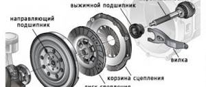
10. Clutch
10.0 Clutch 10.1 Design description 10.2 Adjusting the clutch release drive 10.3 Bleeding the hydraulic clutch 10.4 Removing the master cylinder of the hydraulic clutch 10.5 Removing the flexible hose of the hydraulic clutch 10.6 Removing the working cylinder of the hydraulic clutch on a car with the UMPO-331 engine 10.7 Removing the working cylinder of the hydraulic clutch and the clutch on a car with a VAZ engine -2106 10.8 Replacing the casing and driven disc of the clutch on a car with an UMPO-331 engine 10.9 Replacing the casing and driven disc of the clutch on a car with a VAZ-2106 engine
11. Gearbox IZH-2126
11.0 IZH-2126 gearbox 11.1 Design description 11.2 Oil change 11.3 Replacing the secondary shaft oil seal 11.4 Removing the speedometer drive 11.5 Removing and installing the gearbox on a car with an UMPO-331 engine 11.6 Removing and installing the gearbox on a car with a VAZ-2106 engine 11.7 Replacing the oil seal gearbox input shaft on a car with an UMPO-331 engine 11.8 Replacing the gearbox input shaft oil seal on a car with a VAZ-2106 engine 11.9 Replacing the front bearing of the gearbox input shaft
12. Gearbox VAZ-21074
12.0 VAZ-21074 gearbox 12.1 Design description 12.2 Oil change 12.3 Replacing the input shaft oil seal 12.4 Replacing the secondary shaft oil seal 12.5 Removing the speedometer drive 12.6 Removing the gearbox 12.7 Removing the front bearing of the gearbox input shaft 12.8 Disassembling and assembling the gearbox
13. Cardan transmission
13.0 Cardan transmission 13.1 Design description 13.2 Lubricating the spline joint of the cardan shaft 13.3 Removing the cardan drive 13.4 Replacing the oil seal of the spline joint of the elastic coupling flange and the shank of the front propeller shaft 13.5 Removing the elastic coupling 13.6 Disassembling the universal joint 13.7 Replacing the intermediate support
14. Rear axle
14.0 Rear axle 14.1 Design description 14.2 Changing the oil in the rear axle 14.3 Removing the axle shaft and replacing the oil seal 14.4 Replacing the main gear drive gear oil seal 14.5 Removing the rear axle beam 14.6 Dismantling and assembling the rear axle gearbox
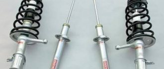
15. Front suspension
15.0 Front suspension 15.1 Design description 15.2 Front wheel alignment angles 15.3 Removing the ball joint 15.4 Removing the lever 15.5 Removing the anti-roll bar 15.6 Removing the spring strut guide 15.7 Replacing the hub bearing 15.8 Removing the subframe
16. Rear suspension
16.0 Rear suspension 16.1 Design description 16.2 Removing the shock absorber 16.3 Removing the spring 16.4 Removing the upper rod 16.5 Removing the lower rod 16.6 Removing the cross rod
17. Steering
17.0 Steering 17.1 Design description 17.2 Adjusting the steering mechanism 17.3 Removing the steering wheel 17.4 Removing the steering column 17.5 Removing the lower universal joint 17.6 Removing the outer tie rod end 17.7 Replacing the rack cover 17.8 Removing the steering mechanism 17.9 Dismantling the steering gear
18. Brake system
18.0 Brake system 18.1 Description of the structure 18.2 Brake pumping 18.3 Front brake pads 18.4 Replacing the rear brake pads 18.5 Removing the main brake cylinder 18.6 Removing the vacuum brake amplifier and adjusting the free stroke of the brake pedal 18.7 Removing the pedal unit 18.8 Removing the front brake hose.
19. Electrical equipment
19.0 Electrical equipment 19.1 General information 19.2 Replacing fuses and relays 19.3 Removing the mounting block 19.4 Ignition switch 19.5 Removing the ignition switch 19.6 Battery 19.7 Cooling system fan electric motor 19.8. Generator 19.9. Starter 10/19. Headlights 19.15. Control devices 19.16. Forced idle economizer control system (EFH)
20. Body
20.0 Body 20.1 Design description 20.2 Removing the radiator grille 20.3 Removing the hood lock 20.4 Removing the hood 20.5 Removing the engine splash guard 20.6 Removing the front bumper 20.7 Removing the front fender 20.8 Replacing the windshield 20.9 Removing the outside rear view mirror
21. Ventilation and heating system
21.0 Ventilation and heating system 21.1 Design description 21.2 Removing the heater valve 21.3 Removing the air blower and heater fan 21.4 Removing the additional heater fan resistor 21.5 Removing the heater radiator 21.6 Removing the heater housing, heater control unit and instrument panel air ducts 21.7 Removing the air supply duct to the rear of the cabin
22. Design features of the IZH-2717 car
22.0 Design features of the IZH-2717 car 22.1 Design features 22.2 Elements of the exhaust gas exhaust system 22.3 Removing the rear suspension shock absorber 22.4 Removing the spring 22.5 Removing the rear light, replacing lamps 22.6 Removing the license plate lamps 22.7 Removing the gas-filled stops of the hood door 22.8 Removing the hood door lock ka and him drives 22.9 Removing the hood door
23. Application
23.0 Appendix 23.1 Diagnosis of engine faults and its systems 23.2 Diagnosis of clutch faults 23.3 Diagnosis of gearbox faults 23.4 Diagnosis of driveline, rear axle, chassis, steering and brake system faults 23.5 Diagnosis of body faults 23.6 Diagnosis of generator faults 23.7 Diagnosis of battery faults 23.8 Diagnostics ignition system malfunctions 23.9 Diagnosis of starter malfunctions
24. Car body care
24.0 Car body care 24.1 Body wash 24.2 Preservation and protection of paintwork