Replacing the clutch disc on a VAZ-2104-2107
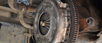
Clutch kit The clutch is the most important component of a car, without which it is impossible to imagine the operation of the gearbox mechanism, as well as the car’s performance of such operations as starting and braking to a final stop. In other words, the clutch is a necessary mechanism of any car, which is a kind of transfer point between the engine and the drive axles.
This unit includes:
- driven clutch disc;
- clutch basket and release bearing with clutch.
So what is this component of the clutch mechanism? This is a disc with spring plates and friction linings that are not connected to each other and are made of a material comparable to the material of the brake pads, i.e. abrasion resistant. In the center of the disk there is a hub with a splined connection.
Clutch device
Clutch adjustment on a VAZ 2106
How to adjust the clutch pedal travel on a VAZ 2106 is quite a pressing question. To cope with this, knowing the required values of the gaps between the moving parts of the clutch cylinder, it will not be difficult to make a similar adjustment of the VAZ clutch with your own hands, you only need to have the following tools:
- wrenches for “10”, “13” and “17”;
- pliers;
- emphasis;
- ruler.
Clutch adjustment on a VAZ 2106 occurs as follows:
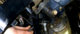
1. The gap between the pusher and the piston is set in the range from 0.1 to 0.5 mm. The gap is set using a nut on the clutch pedal travel limiter. To do this, you will need to loosen the locknut by screwing in or out the limiter. After setting the gap to 0.4-2 mm, the limiter must be tightened again with a lock nut. All this work is carried out from inside the car under the steering column.
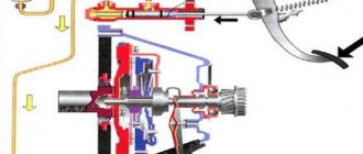
_1 – main cylinder body; 2 – bypass (compensation) hole; 3 – fitting gasket; 4 – fitting; 5 – lock spring washer; 6 – piston of the main cylinder; 7 – sealing ring; 8 – pusher piston; 9 – hook; 10 – pedal axis; 11 – bracket for clutch and brake pedals; 12 – clutch pedal servo spring; 13 – clutch pedal release spring; 14 – clutch pedal travel limiter; 15 – clutch pedal; 16 – piston pusher; 17 – protective cap; 18 – retaining ring; 19 – inlet; 20 – sealing ring (ring valve); 21 – piston bypass hole; 22 – working cavity of the cylinder; 23 – spring; 24 – gasket; 25 – plug._
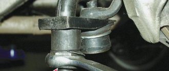
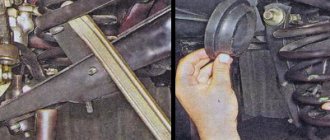
2.To ensure smooth operation of the clutch, you need to adjust the free play of the fork pusher. It should be 4-5 mm. To carry out this procedure, you will need to remove the spring and install a ruler along the pusher. After this, mark the minimum and maximum travel of the fork pusher. Calculate the stroke in millimeters. If there are deviations, then adjustment is required. This is done by tightening or loosening the nut on the pusher.
_1 – clutch release bearing; 2 – ball joint; 3 – clutch release fork;_4 – pusher; 5 – adjusting nut; 6 – lock nut; 7 – tension spring; 8 – housing plug; 9 – fitting for bleeding; 10 – cylinder body; 11 – sealing ring; 12 – protective cap; 13 – piston; 14 – seal; 15 – plate; 16 – spring; 17 – support washer; 18 – retaining ring.
The normal clutch pedal travel is 25-35 mm. It is worth clarifying that the adjustment process itself is not simple and can take quite a lot of time. When performing any action, try to be extremely focused.
Author: Ivan Matieshin
Malfunctions
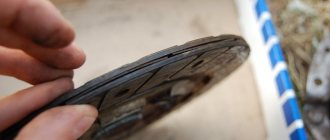
As a result of vehicle operation, the clutch disc, like any consumable material, can become unusable - the springs weaken, the friction linings wear out and become thinner. Manufacturers do not indicate a specific service life of the disk, because it depends only on the driver: one “clutch” can last only 5,000 km, while another can last 100,000. Increased clutch wear can result from:
- sudden starting at high speeds;
- slip;
- incorrect adjustment;
- participation in racing events;
- leakage of foreign liquids.
Usually there are two faults for which it is worth considering repairs:
- the clutch “slips”;
- the clutch “drives”.
When slipping, the driven disk is not pressed completely against the flywheel. What does this mean? If you sharply press the gas pedal while the car is moving, you may notice an increase in engine speed, but there will be no increase in speed. In the end, the car will someday just stand up and only towing or muscle power can set it in motion. Therefore, the issue of replacing the driven disk should not be shelved.
When the clutch “drives”, uncharacteristic sounds and noises are observed when changing gears, gears are difficult to engage. In this case, the driven disk, on the contrary, does not completely “separate” from the flywheel. In this case, pumping the hydraulics and adjusting the free play of the clutch helps, which can be easily done by anyone in a garage. If you ignore this malfunction, you can run into expensive gearbox repairs.
Clutch kit price
Now, in the era of the development of the Internet, there is no need to run to stores and look for the necessary spare part. It is enough to have access to the World Wide Web and you will have any detail in a couple of clicks. Prices for clutch discs for the VAZ-2107 vary from 470 to 2000 rubles. The cost of replacement work in Moscow and the Moscow region is 2–2.5 thousand rubles.
What advice can you give when choosing a disk? First, rummage through the forums and read reviews. Secondly, when purchasing a disc, do not be lazy to inspect it. Examine the splines especially carefully - there should be no nicks or burrs there, otherwise there is a risk that the disk simply will not fit on the shaft or will not be removed during the next replacement.
Take a look at the friction linings: they should all be uniform in composition and free of cracks. Another point is the quality of the riveting. The key to quality here is the identical dimensions of the flange. Try to swing the damper springs; if there is play, then you should refuse the purchase. And the last thing worth paying attention to is the presence of markings on the damper plate.
Clutch VAZ 2106 Zhiguli
- Repair manuals
- Repair manual for VAZ 2106 (Zhiguli) 1976-2005.
- Clutch
8.0 Clutch Clutch with hydraulic release 1 - adjusting nut;
2 - lock nut; 3 — tension spring; 4 – piston of the clutch working cylinder; 5 - working cylinder; 6 — bleeder fitting; 7 - flywheel; 8 — hydraulic clutch pipeline; 9 - crankshaft; 10 – master cylinder reservoir; 11 ... 8.1 Replacing fluid and bleeding the clutch hydraulic drive PERFORMANCE ORDER It is recommended to replace the fluid in the clutch hydraulic drive every five years of vehicle operation. We pump the hydraulic drive when air gets into the system for one reason or another. The presence of air in the hydraulic drive leads to incomplete disengagement of the clutch (with...
8.2 Adjusting the drive PERFORMANCE ORDER Adjusting the clutch drive consists of ensuring clearances between the pusher and the master cylinder piston and between the clutch release bearing and the friction ring of the thrust flange. The gap between the pusher and the master cylinder piston should be 0.1–0.5 m...
8.3 Replacing the clutch master cylinder PERFORMANCE ORDER Use a rubber bulb to remove fluid from the clutch hydraulic reservoir. Loosen the band clamp and remove the hose from the cylinder fitting. ...
8.4 Repairing the clutch master cylinder PERFORMANCE ORDER Remove the clutch master cylinder from the car (see Replacing the clutch master cylinder). Using a screwdriver, remove the protective cap from the end of the cylinder. Using an awl, we remove the lock washer... ...and remove the fitting with the sealing gasket. W...
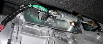
8.5 Replacing the clutch slave cylinder PERFORMANCE ORDER We carry out the work on an inspection ditch or a lift. Disconnect the tension spring. ...
8.6 Replacing the pressure plate assembly and clutch release bearing PERFORMANCE ORDER To access the clutch discs, you need to remove the gearbox (see Replacing the gearbox), but there is a less labor-intensive method. We carry out the work on an inspection ditch or a lift. We disconnect the cardan transmission from the gearbox (see Replacing the cardan transmission), the working ci...
↓ Comments ↓
1. General information
1.0 General information 1.1 Safety precautions
2. Diagnosis of faults
2.0 Diagnostics of faults 2.1 diagnostics of faults in the engine and its systems 2.2 Diagnostics of faults in the clutch 2.3 diagnostics of faults in the gearbox 2.4 Diagnostics of faults in the driveline, rear axle, chassis, steering and braking system 2.5 Diagnosis of faults in the body 2.6. Diagnosis of electrical equipment faults
3. Engine
3.0 Engine 3.1 Cylinder head and timing mechanism 3.2 Lubrication system 3.3 Oil change 3.4 Replacing the camshaft drive chain guide 3.5 Replacing the camshaft and valve levers 3.6 Replacing the valve stem seals 3.7 Replacing the intake and exhaust manifold gaskets 3.8 Replacing the cylinder head gasket ov 3.9 Disassembling the head cylinder block, valve grinding
4. Engine power system
4.0 Engine power system 4.1 Replacing the air filter element 4.2 Replacing the fuel pump 4.3 Repairing the fuel pump 4.4 Replacing the fuel tank and its hatch cover
5. Carburetor
5.0 General information about the carburetor 5.1 Cleaning the fuel filter 5.2 Replacing the idle air system solenoid valve 5.3. Adjusting the carburetor 5.4 Replacing the carburetor 5.5. Carburetor repair
6. Engine cooling system
6.0 Engine cooling system 6.1 Replacing the coolant 6.2 Replacing the coolant pump 6.3. Replacing the thermostat 6.4 Replacing the engine radiator
7. Exhaust system
7.0 Exhaust system 7.1 Replacing exhaust system parts
8. Clutch
8.0 Clutch 8.1 Replacing fluid and bleeding the clutch hydraulic drive 8.2 Adjusting the drive 8.3 Replacing the clutch master cylinder 8.4 Repairing the clutch master cylinder 8.5 Replacing the clutch slave cylinder 8.6 Replacing the pressure plate assembly and clutch release bearing
9. Gearbox
9.0 Gearbox 9.1 Checking the level and changing the oil in the gearbox 9.2 Replacing the reverse light switch 9.3 Replacing the secondary shaft cuff 9.4 Replacing the gearbox 9.5 Repairing the gearbox 9.6 Replacing the speedometer drive 9.7 Features of repairing a five-speed gearbox
10. Cardan transmission
10.0 Cardan transmission 10.1. Maintenance 10.2. Replacing the driveshaft
11. Rear axle
11.0 Rear axle 11.1 Checking the serviceability of the rear axle 11.2 Changing the oil 11.3 Replacing the axle shaft and its cuff 11.4 Removing and installing the rear axle 11.5 Replacing the cuff of the drive gear 11.6 Replacing the gearbox 11.7 Repairing the gearbox
12. Front suspension
12.0 Front suspension 12.1. Maintenance 12.2 Replacing the bearings and hub cuff 12.3 Replacing the cushions and stabilizer bar 12.4 Replacing the ball joints 12.5 Replacing the shock absorbers 12.6 Replacing the springs 12.7 Replacing the upper arms and their rubber-metal hinges 12.8 Replacing the rubber-metal joints of the lower arms on a car 12.9 Replacing the lower arms 12.12 . Adjusting wheel alignment angles
13. Rear suspension
13.0 Rear suspension 13.1 Checking technical condition 13.2. Replacement of rear suspension parts
14. Steering
14.0 Steering 14.1 Adding oil 14.2 Checking the condition of the steering 14.3 Adjusting the gear engagement 14.4 Replacing steering rods 14.5 Replacing and repairing the pendulum arm 14.6 Removing and installing the steering wheel 14.7 Removing and installing the steering shaft 14.8 Removing and installing the steering mechanism 14.9 Removing the bipod
15. Brake system
15.0 Brake system 15.1 Checking the condition of the hydraulic drive 15.2 Checking the vacuum brake booster 15.3 Checking the functionality of the pressure regulator 15.4 Replacing brake fluid and bleeding the brake system 15.5 Replacing the brake pads of the front wheels 15.6 Replacing the brake pads of the rear wheels 15.7 Replacing the brake caliper of the front wheel 15.8 Replacing the brake cylinders of the front wheels 15 .9 Repair of front wheel brake cylinders
16. General information
16.0 General information 16.1. Checking electrical circuits 16.2 Fuse blocks 16.3 Replacing fuses 16.4 Replacing the main and additional fuse blocks 16.5. Replacing the relay 16.6 Replacing the ignition switch 16.7 Replacing the contact part of the ignition switch 16.8 Battery 16.9. Generator 16.10. Starter 16.11. Ignition system 16.12. Lighting, light and sound alarms 16.13. Windshield cleaner and washer 16.14. Repair of the electric heater motor 16.15. Control devices
17. Body
17.0 Body 17.1 Replacing the front bumper 17.2 Replacing the radiator grille 17.3 Replacing the hood latch 17.4 Replacing the hood 17.5 Replacing the windshield 17.6 Replacing the interior rear view mirror 17.7 Replacing the sun visor 17.8 Replacing the headliner 17.9 Replacing the ceiling grab handle
18. Heating and ventilation system
18.0 Heating and ventilation system 18.1 Replacing the electric heater fan 18.2 Replacing the heater radiator 18.3 Replacing the radiator casing 18.4 Replacing the heater valve
19. Car body care
19.0 Car body care 19.1 Car washing 19.2 Preservation and protection of paintwork
20. Applications
20.0 Applications 20.1 Tools used in addition to the standard set 20.2 Electrical diagram of VAZ-2106, VAZ-21061, VAZ-21063 cars produced in 1976–1987. 20.4 Tightening torques for threaded connections 20.5 Basic data for adjustments and monitoring 20.6 Characteristics of spark plugs 20.7 Fuel, lubricants and operating fluids used 20.8 Lamps used on the vehicle 20.9 Lip seals (oil seals)