Despite the fact that the VAZ-2106 car has a carburetor power system, there are still sensors in the car. They measure the pressure and temperature of the coolant. Let's talk about the temperature sensor VAZ-2106. It is installed in the car's cooling system and is connected to the temperature scale in the cabin.
Purpose
So, what functions does the sensor perform? This element is necessary to control the coolant temperature, so that in case of overheating the driver can react to the situation in time. Information from the sensor is displayed on the instrument panel. The driver can observe how hot or cold the coolant is in the engine system. In this car, the VAZ-2106 temperature sensor no longer performs any functions.
Device
If we consider the device, there are two types of temperature sensors. The first is a thermistor. This is a thermal resistor whose resistance changes as the temperature increases or decreases. The thermistor is located inside a threaded metal housing. There is a plastic tail part on the body. Contacts are installed at the rear. There is one contact (positive) on the tail section. It goes to the dashboard. The role of the second contact is performed by the housing - it is connected to the total mass.
The second type of sensor is a special contactor with a bimetallic strip inside. The latter, depending on the heating of the antifreeze, closes or opens.
The first temperature sensor of the VAZ-2106 is used only to display data on the heating of antifreeze in the cooling system. As the temperature rises, the resistance of the sensor changes. A certain voltage is applied to the instrument scale. The device is installed in the engine cylinder block in the channels of the cooling system.
The second temperature sensor is designed a little differently. It also reacts to the temperature of antifreeze or antifreeze, but is designed to turn on the electric fan on the radiator. This sensor is installed on the radiator.
Historical excursion
The VAZ 2103 car was a luxury version of the VAZ 2101, which was initially planned for production at the Tolyatti plant as part of the overall plan for the production of cars. That is why:
- Vehicle components and parts are 80% unified;
- The appearance is different according to the development concept of the luxury model.
The progenitor of the Zhiguli family – Fiat 125
The price of the VAZ 2103 was higher precisely due to improvements in the interior and exterior. But due to the complete unification of the parts of the two models, the cost of the cars was almost equal.
For reference: Fiat 124 as a prototype of the VAZ 2101 and Fiat 125 as a platform for the VAZ 2103 were thoroughly modified by the Italian side at the request of domestic engineers.
Read also about the features of the VAZ 2101 wiring diagram.
External changes
Changes in appearance have led to the fact that the wiring of the VAZ 2103 has been radically redesigned. In particular:
- The use of dual headlights required an additional wiring harness at the front of the vehicle;
- The block-type brake lights also required upgrading the wiring in the rear of the car;
- Turn signal indicators were located at the ends of the wings, and on the front part they were duplicated in one block with side lights. Accordingly, the electrical wiring on the VAZ 2103 was modified to take these changes into account.
The change in appearance also affected the electrical circuit - the wiring on the VAZ 2103 has been redesigned
Internal differences in electrical circuits
In contrast to the “norm” standard, on luxury models, to which the VAZ 2103 belonged, an increase in functionality was required. In particular:
- Installation of an electric windshield washer required an upgrade to the electric windshield wiper control unit on the steering column;
- An electronic tachometer has been added to the instrument scale, and the instrument scale itself has undergone visual changes;
- There were additional warning lamps and an electric clock on the dashboard;
- The installation of an alarm system as part of the VAZ 2103 has become the norm (it was not installed on the VAZ 2101).
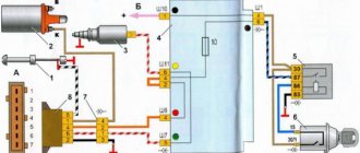
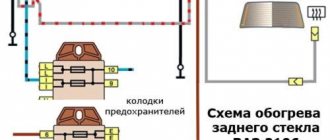
Electrical wiring of VAZ 2103: diagram of hazard warning lights and direction indicators
The photo shows:
- Brown shows the circuit from the battery terminal “+” through the generator (terminal “30”) and the fuse box (No. 6) to the ignition switch (pin 30/1);
- Blue and black colors show the circuit from the hazard warning button (pin No. 1 of the terminal block) to the three-lever steering column switch and further through the ignition switch (pin 15) and the fuse block (No. 10) to the sidelights and side turn signals;
- The circuit from the breaker relay to the hazard warning light button and the three-lever steering column switch is shown in pink.
Read also about the features of the unification of electrical wiring Niva 21213.
Principle of operation
For normal operation of the VAZ-2106 cooling temperature sensor, a voltage of 5 V is required. Since the thermistor has a negative temperature coefficient, as the antifreeze heats up, the resistance on the sensor will drop. Accordingly, the tension will decrease. The instrument panel determines the temperature based on the level of voltage drop.
In different VAZ models, the sensor can be located in different places - in the cylinder head, in the thermostat housing or on its body. The element must be placed in the area of the outlet hose, which is needed for the passage of fluid into the radiator. In the VAZ-2106, DTOZH can be found in the cylinder head.
Connection
Connecting the VAZ-2106 temperature sensor is extremely simple. There is a single contact on the tail part of the DTOZH, screwed into the cylinder block. It is connected to the wire going to the dashboard. It has a corresponding terminal. To connect, just connect the terminal to the contact on the sensor, and then the dashboard will show the heating of the coolant, and therefore the engine temperature.
Electrical diagram of VAZ-2106 (produced 1976-1987)
Electrical diagram of VAZ-2106 (produced 1976-1987)
Repair and operation manual - Electrical diagrams of VAZ-2101 - VAZ-2107 - Electrical diagram of VAZ-2106, VAZ-21061, VAZ-21063 cars produced in 1976-1987.
Electrical diagram of VAZ-2106, VAZ-21061, VAZ-21063 cars produced in 1976-1987.
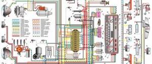
Diagram of electrical equipment of VAZ-2106, VAZ-21061, VAZ-21063 cars produced in 1976-1987.
1 – front lights; 2 – side direction indicators; 3 – battery; 4 – battery charge warning lamp relay; 5 – relay for turning on low beam headlights; 6 – relay for turning on the high beam headlights; 7 – starter; 8 – generator; 9 – external headlights; 10 – internal headlights; 11 – sound signals; 12 – electric motor of the engine cooling system fan; 13 – fan motor activation sensor; 14 – ignition coil; 15 – ignition distributor; 16 – spark plugs; 17 – carburetor solenoid valve; 18 – coolant temperature indicator sensor; 19 – engine compartment lamp; 20 – reverse light switch; 21 – oil pressure indicator sensor; 22 – oil pressure warning lamp sensor; 23 – brake fluid level warning lamp sensor; 24 – windshield wiper motor; 25 – windshield washer electric motor; 26 – relay for turning on sound signals; 27 – relay for turning on the fan motor; 28 – voltage regulator; 29 – windshield wiper relay; 30 – additional fuse block; 31 – main fuse block; 32 – relay-interrupter for alarm and direction indicators; 33 – brake light switch; 34 – plug socket for a portable lamp; 35 – heater electric motor; 36 – additional resistor of the heater electric motor; 37 – hours; 38 – heater motor switch; 39 – glove box lighting lamp; 40 – cigarette lighter; 41 – alarm switch; 42 – instrument lighting switch; 43 – indicator lamp for insufficient brake fluid level; 44 – three-lever switch; 45 – ignition switch; 46 – reverse light switch; 47 – external lighting switch; 48 – lamp switches located in the front door pillars; 49 – switches for warning lights of open front doors; 50 – alarm lights for open front doors; 51 – lamp switches located in the rear door pillars; 52 – parking brake warning lamp switch; 53 – interior lamps; 54 – fuel level indicator with reserve warning lamp; 55 – coolant temperature indicator; 56 – oil pressure gauge with insufficient pressure warning lamp; 57 – tachometer; 58 – parking brake warning lamp; 59 – battery charge indicator lamp; 60 – control lamp for the carburetor air damper; 61 – side light indicator lamp; 62 – indicator lamp for direction indicators; 63 – headlight high beam indicator lamp; 64 – speedometer; 65 – carburetor air damper warning lamp switch; 66 – relay-interrupter for the parking brake warning lamp; 67 – rear lights; 68 – license plate lights; 69 – sensor for level indicator and fuel reserve; 70 – trunk lighting lamp; 71 – rear fog lamp*. The order of conventional numbering of plugs in the blocks: a – windshield wiper and windshield wiper breaker relay; b – hazard warning and direction indicator breaker relay; c – three-lever switch.
* Installed on parts of manufactured cars.
Quote
Symptoms of a problem
The VAZ-2106 temperature sensor is a practically fail-safe device. Its design is very simple. Hence such reliability. But even with it, motorists may have problems. The reliability of modern spare parts leaves much to be desired.
Problems with the sensor boil down to violation of readings, violation of calibration and resistance. But the only trouble is the risk of engine overheating, since the driver does not see the real temperature. On injection cars, the damage from a broken sensor will be much greater - there the sensor is also connected to the ECU, and the proportions of mixture formation depend on the engine temperature.
If we talk about another VAZ-2106 temperature sensor, which is responsible for turning on the fan, then its malfunction can lead to disastrous consequences. Due to the exceeded temperature of its activation, the fan will not work on time. In order for the cylinder head to overheat and begin to deform, the temperature needs to rise only a couple of degrees above normal. The second malfunction that can lead to no readings on the dashboard is a break in the wiring to the sensor.
How to check?
Since the VAZ-2106 coolant temperature sensor is extremely simple, the methods for diagnosing it are extremely simple. But before diagnosing the element, you should inspect the wiring and its integrity. You can also check whether voltage is coming to the sensor.
The most accurate way to check functionality is to measure the resistance using a multimeter. But during the measurement process, the element will have to be boiled in water. As the temperature changes, the resistance of the sensor will change. But since in the VAZ-2106 the DTOZH does not affect anything, it is easier to simply replace the faulty element. Moreover, its price is not higher than two hundred rubles.
Electrical circuit diagram for VAZ 2106, 21061, 21063, 21065 produced in 1988-2001.
This page contains a diagram of the electrical equipment of the VAZ 2106 car and its modifications (21061, 21063, 21065), which was produced between 1988 and 2001.
To enlarge the image, click on the image below.
Electrical diagram of VAZ 2106 produced 1988-2001
- front lights
- side direction indicators
- accumulator battery
- Battery indicator lamp relay
- low beam headlight relay
- headlight high beam relay
- starter
- generator
- exterior lights
- interior lights
- Fan motor switch sensor
- engine cooling fan motor
- sound signal
- ignition coil
- distributor
- spark plug
- carburetor solenoid valve
- coolant temperature gauge sensor
- engine compartment lamp
- reverse light switch
- oil pressure indicator sensor
- low oil pressure warning sensor
- low brake fluid level indicator sensor
- windshield wiper motor
- switch*
- windshield washer motor
- fan motor relay**
- voltage regulator
- windshield wiper relay
- additional fuse box
- main fuse box
- hazard warning and direction indicator relay
- rear window heating relay ***
- brake light switch
- socket for portable lamp ****
- additional resistor for heater motor
- heater motor
- heater motor switch
- watch
- glove compartment lamp
- cigarette lighter
- hazard switch
- instrument lighting regulator
- brake fluid level indicator lamp
- three lever switch
- ignition switch
- heated rear window switch ***
- rear fog light switch
- outdoor light switch
- lamp switches located in the front door pillars
- gear motors for electric windows of front doors ***
- lamp switches located in the rear door pillars
- Parking brake warning light switch
- interior lamps
- fuel level indicator with reserve indicator
- coolant temperature gauge
- oil pressure indicator with low pressure indicator
- tachometer
- parking brake warning lamp
- battery charge indicator lamp
- carburetor choke warning lamp
- side light indicator lamp
- turn signal lamp
- high beam warning lamp
- speedometer
- carburetor choke warning switch
- Left front door power window switch ***
- front door power window relay ***
- Right front door power window switch ***
- tail lights
- license plate lights
- level indicator and fuel reserve sensor
- pads connected to the rear window heating element***
- trunk light
- rear fog light
In order to download the VAZ 2106 diagram and save it to your computer, hover your cursor over the image above, then right-click and select “save as image.”
The order of conditional numbering of plugs in blocks:
- a - switch
- b — ignition distributor sensor
- c - windshield wiper and windshield wiper breaker relay
- g - hazard warning and turn signal breaker relay
- d - three-lever switch
* — Installed if a non-contact ignition system is used on the vehicle. In this case, an ignition distributor sensor of type 38.3706 and an ignition coil of type 27.3705 or 027.3705 must be installed.
** - Since 2000, it has not been installed and electric motor 12 is switched on directly by sensor-switch 11. In this case, instead of the previously used temperature sensor 11 of type TM-108, sensor-switch 661.3710 is used.
*** — Installed on parts of cars.
**** — Not installed since 2000.
How to replace an element?
To replace the VAZ-2106 engine temperature sensor, it is enough to cool the engine if it was previously heated. In the process, you will have to unscrew the element from the cylinder head cooling jacket, and you can get burned by the hot liquid. The sensor has an M14 thread. In order to unscrew it, you will need a 19mm wrench. The faulty element is unscrewed, and a new one is screwed in its place. In some cars, it is recommended to drain the coolant a little before replacing it.
You can replace the sensor with any one that is sold in the store and fits the thread in the cylinder head. The main thing is that the contacts on the element are similar to the plug in the car wiring. Then everything will connect and work without any problems.
Electrical diagram of VAZ-2103
Electrical diagram of VAZ-2103
Repair and operation manual - Electrical diagrams of VAZ-2101 - VAZ-2107 - Electrical diagram of the VAZ-2103 car
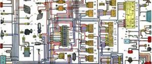
Electrical diagram of the VAZ-2103 car.
1 – sound signals;
2 – headlights; 3 – front lights; 4 – side direction indicators; 5 – battery; 6 – battery charge warning lamp relay; 7 – carburetor solenoid valve; 8 – generator; 9 – engine compartment lamp; 10 – starter; 11 – spark plugs; 12 – electric motor of the engine cooling system fan; 13 – fan motor activation sensor; 14 – ignition distributor; 15 – oil pressure indicator sensor; 16 – oil pressure warning lamp sensor; 17 – brake fluid level warning lamp sensor; 18 – voltage regulator; 19 – fan motor fuse; 20 – coolant temperature indicator sensor; 21 – windshield wiper motor; 22 – ignition coil; 23 – windshield washer electric motor; 24 – relay for turning on sound signals; 25 – relay for turning on the high beam headlights; 26 – relay for turning on the fan electric motor; 27 – block for the windshield wiper switch in the foot washer pump (installed before 1980); 28 – windshield wiper relay; 29 – plug socket for a portable lamp; 30 – brake light switch; 31 – fuse block; 32 – reverse light switch; 33 – relay-interrupter of direction indicators; 34 – additional resistor of the heater electric motor; 35 – heater electric motor; 36 – hours; 37 – glove box lighting lamp; 38 – cigarette lighter; 39 – heater motor switch; 40 – windshield wiper and washer switch; 41 – switch for headlights, direction indicators and sound signals; 42 – ignition switch; 43 – instrument lighting switch; 44 – external lighting switch; 45 – front door open alarm light switch; 46 – signaling lamp for an open front door; 47 – lamp switches located in the front door pillars; 48 – lamp switches located in the rear door pillars; 49 – interior lamps; 50 – instrument lighting lamp; 51 – fuel level indicator with reserve indicator lamp; 52 – coolant temperature indicator; 53 – oil pressure gauge with insufficient pressure warning lamp; 54 – parking brake warning lamp; 55 – battery charge indicator lamp; 56 – control lamp for the carburetor air damper; 57 – tachometer; 58 – side light indicator lamp; 59 – turn signal indicator lamp; 60 – control lamp for high beam headlights; 61 – speedometer; 62 – switch for the carburetor air damper warning lamp; 63 – relay-interrupter for the parking brake warning lamp; 64 – parking brake warning lamp switch; 65 – rear lights; 66 – sensor for level indicator and fuel reserve; 67 – license plate light; 68 – trunk lighting lamp; 69 – reversing lamp; A – diagram of the conditional numbering of plugs in the blocks of the relay-breaker and windshield wiper. Quote