Similarities and differences between contactors and starters
Both devices serve to close and open the circuit as needed. Their design is based on an electromagnet; they operate on both alternating and direct current. Equipped with power, or main, as well as signal, or auxiliary, contacts.
The difference lies in the degree of protection of the devices. Contactors are equipped with a chamber for extinguishing the arc. Due to this feature, they are used in circuits with higher power than starters. In addition, the device itself is more massive due to arc suppression chambers. The maximum permissible current for starters is up to 10 amperes.
The starters are made in a plastic case and are equipped with eight contacts - six for powering a three-phase motor, and two for providing it with power after the “start” button is stopped pressing. They are used both to power electric motors and devices for which this circuit is suitable.
Contactors are often manufactured without a housing, so during operation it is necessary to provide them with a protective casing that protects it from moisture and contamination, and electric shock to people.
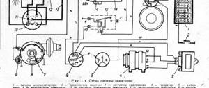
Standard switching diagram for magnetic starters
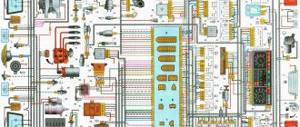
This starter connection diagram is required in order to start the engine through the starter using the “Start” button and de-energize this engine with the “Stop” button. This is easier to understand if you divide the circuit into two parts: the power circuit and the control circuit. The power part of the circuit should be powered with a three-phase voltage of 380 V, having phases “A”, “B”, “C”. The power part consists of a three-pole circuit breaker, power contacts of the magnetic starter “1L1-2T1”, “3L2-4T2”, “5L3-6L3”, as well as an asynchronous three-phase electric motor “M”.
The control circuit is supplied with 220 volt power from phase “A” and to the neutral. The control circuit diagram includes the “Stop” button “SB1”, “Start” “SB2”, the coil “KM1” and the auxiliary contact “13HO-14HO”, which is connected in parallel with the contacts of the “Start” button. When the circuit breaker of phases “A”, “B”, “C” is turned on, the current passes to the contacts of the starter and remains on them. The supply control circuit (phase “A”) passes through the “Stop” button to contact 3 of the “Start” button, and in parallel to the auxiliary contact of the 13HO starter and remains there on the contacts. If the “Start” button is activated, voltage comes to the coil - phase “A” from the starter “KM1”. The starter electromagnet is triggered, the contacts “1L1-2T1”, “3L2-4T2”, “5L3-6L3” are closed, after which a voltage of 380 volts is supplied to the engine according to this connection diagram and the electric motor begins to operate. When the “Start” button is released, the starter coil supply current flows through contacts 13HO-14HO, the electromagnet does not release the starter power contacts, and the engine continues to operate. When the “Stop” button is pressed, the power supply circuit of the starter coil is de-energized, the electromagnet releases the power contacts, voltage is not supplied to the engine, and the engine stops.
You can also watch the video to see how to connect a three-phase motor:
How does a starter work?
The main parts of the device are an inductive coil and a magnetic circuit, consisting of static and dynamic W-shaped parts. They are located with leads facing one another. The stationary part is fixed to the body, and the movable part is not fixed. At the bottom of the magnetic circuit, an inductance coil is inserted into a special slot.
Depending on its parameters, the nominal operating voltage of the device changes - from 12 to 380 volts. At the top of the magnetic circuit there are two pairs of contacts - static and dynamic.
When there is no power, a spring keeps the contacts open. When power appears, a magnetic field is induced in the coil, and the upper core is attracted to the lower one. As a result, the contacts are closed. After removing the power, the electromagnetic field also disappears, and the spring opens the contacts.
The device can operate from a direct current source, and with single- and three-phase alternating current, the main thing is that its values do not exceed the rating specified by the manufacturer.
Purpose and device
Magnetic starters are built into power networks to supply and disconnect power. They can work with alternating or direct voltage. The work is based on the phenomenon of electromagnetic induction; there are working (power is supplied through them) and auxiliary (signal) contacts. For ease of use, Stop, Start, Forward, Back buttons are added to the magnetic starter switching circuits.
This is what a magnetic starter looks like
Magnetic starters can be of two types:
- With normally closed contacts. Power is supplied to the load constantly and is turned off only when the starter is triggered.
- With normally open contacts. Power is supplied only while the starter is running.
The second type is more widely used - with normally open contacts. After all, basically, devices should work for a short period of time, the rest of the time they should be at rest. Therefore, next we will consider the principle of operation of a magnetic starter with normally open contacts.
Composition and purpose of parts
The basis of a magnetic starter is an inductance coil and a magnetic circuit. The magnetic core is divided into two parts. Both of them have the shape of the letter “W”, installed in a mirror image. The lower part is stationary, its middle part is the core of the inductor. The parameters of the magnetic starter (the maximum voltage with which it can operate) depend on the inductor. There may be starters of small ratings - 12 V, 24 V, 110 V, and the most common - 220 V and 380 V.
Magnetic starter (contactor) device
The upper part of the magnetic circuit is movable, with movable contacts attached to it. The load is connected to them. Fixed contacts are fixed to the starter body and are supplied with supply voltage. In the initial state, the contacts are open (due to the elastic force of the spring that holds the upper part of the magnetic circuit), power is not supplied to the load.
Principle of operation
In the normal state, the spring lifts the upper part of the magnetic circuit, the contacts are open. When power is applied to a magnetic starter, the current flowing through the inductor generates an electromagnetic field. Compressing the spring, it attracts the moving part of the magnetic circuit, the contacts close (the picture on the right). Through closed contacts, power is supplied to the load, it is in operation.
Operating principle of a magnetic starter (contactor)
When the power to the magnetic starter is turned off, the electromagnetic field disappears, the spring pushes the upper part of the magnetic circuit up, the contacts open, and power is not supplied to the load.
AC or DC voltage can be supplied through a magnetic starter. Only its size is important - it should not exceed the nominal value specified by the manufacturer. For alternating voltage the maximum is 600 V, for direct voltage - 440 V.
220 volt network
When powered from a 220 volt single-phase network, the connection is made through the terminals, which are usually designated A1 and A2. They are located at the top of the starter housing. When a wire with a plug is connected to them, the device is connected to the network. The terminals marked L1, L2, L3 are supplied with any voltage removed from contacts T1, T2 and T3.
When connecting to a device, zero and phase can be easily transferred, this is not important. Typically, power is supplied through a temperature or light level sensor, for example, when connecting the starter to autonomous heating or street lighting.
What is an intermediate relay: design, principle of operation, device and application ideas (115 photos)Homemade 12 volt power supply: selection of components and simple circuits for creating with your own hands. 130 photos of homemade universal blocks
How a voltage control relay works: the principle of operation of the protection and the nuances of connecting a control relay for a house or apartment
Connection diagram for a starter with a 220 V coil
In any magnetic starter connection diagram there are two circuits. One power line through which power is supplied. The second is a signal one. This circuit controls the operation of the device. They need to be considered separately - it’s easier to understand the logic.
At the top of the magnetic starter housing there are contacts to which the power for this device is connected. The usual designation is A1 and A2. If the coil is 220 V, 220 V is supplied here. It makes no difference where to connect “zero” and “phase”. But more often the “phase” is supplied to A2, since here this output is usually duplicated in the lower part of the case and quite often it is more convenient to connect here.
Connecting power to the magnetic starter
Below on the case there are several contacts labeled L1, L2, L3. The power supply for the load is connected here. Its type is not important (constant or alternating), it is important that the rating is not higher than 220 V. Thus, voltage from a battery, wind generator, etc. can be supplied through a starter with a 220 V coil. It is removed from contacts T1, T2, T3.
Purpose of magnetic starter sockets
The simplest scheme
If you connect a power cord (control circuit) to pins A1 - A2, apply 12 V voltage from the battery to L1 and L3, and lighting devices (power circuit) to pins T1 and T3, we get a lighting circuit operating on 12 V. This is only one of the options for using a magnetic starter.
But more often, these devices are used to supply power to electric motors. In this case, 220 V is also connected to L1 and L3 (and the same 220 V is removed from T1 and T3).
The simplest diagram for connecting a magnetic starter - without buttons
The disadvantage of this scheme is obvious: to turn the power off and on, you will have to manipulate the plug - remove/insert it into the socket. The situation can be improved if you install an automatic machine in front of the starter and turn on/off the power supply to the control circuit with its help. The second option is to add buttons to the control circuit - Start and Stop.
Diagram with “Start” and “Stop” buttons
When connected via buttons, only the control circuit changes. The strength remains unchanged. The entire connection diagram of the magnetic starter changes slightly.
The buttons can be in a separate case, or in one. In the second version, the device is called a “push-button post”. Each button has two inputs and two outputs. The “start” button has normally open contacts (power is supplied when it is pressed), the “stop” button has normally closed contacts (the circuit breaks when pressed).
Connection diagram of a magnetic starter with “start” and “stop” buttons
Buttons are built in front of the magnetic starter in series. First - “start”, then - “stop”. Obviously, with such a connection scheme for a magnetic starter, the load will only work while the “start” button is held down. As soon as she is released, the food will disappear. Actually, in this version the “stop” button is superfluous. This is not the mode that is required in most cases. It is necessary that after releasing the start button, power continues to flow until the circuit is broken by pressing the stop button.
Start and stop buttons
When starting and stopping the engine using a starter, it is convenient to connect a device with buttons connected in series with the device.
Voltage is supplied to the motor through any contact marked with the letter L, and it is removed from the corresponding contact under the letter T. This connection diagram is valid for a single-phase network.
Starter connection diagram
Switches are used to supply power to various electrical appliances. Depending on the power of the electrical installation, the contacts of the switches are designed: the higher the current (power consumption), the greater the mass and contact area of the metal. Accordingly, the clamping device (spring, steel plate) must provide greater pressing force. If the switch is manual (mechanical), its size will be too large and it will be inconvenient to use.
Such input devices have a number of disadvantages (in addition to dimensions):
- too much effort when turning on (off);
- contact groups are not designed for frequent switching: they wear out quickly;
- safety issues have not been resolved: too much time is wasted when emergency shutdown is necessary;
- “switches” must be placed near the work area (in close proximity to the electrical installation), this is not always convenient due to the same dimensions.
The only way out is to connect the motor (or other electrical appliance) through the starter.
Three-phase network at 380 V
When connected to a three-phase network, three groups of contacts L and T are used. One of the phases is connected to contact A1 or A2, and “zero” is connected to the second of them. To protect the asynchronous motor from overheating, a thermal relay is introduced into the circuit. There are no more fundamental differences in connection.
Reversible switching circuit for magnetic starters
The connection diagram for a reversible magnetic starter is used when it is necessary to ensure rotation of the electric motor in both directions. For example, a reversing starter is installed on an elevator, lifting crane, drilling machine and other devices that require forward and reverse movement.
The reversing starter consists of two ordinary starters assembled according to a special circuit. It looks like this:
The connection diagram for a reversible magnetic starter differs from other circuits in that it has two completely identical starters that operate alternately. When the first starter is connected, the engine rotates in one direction, when the second starter is connected, the engine rotates in the opposite direction. If you look closely at the diagram, you will notice that with variable connection of starters, two phases change places. This causes the three-phase motor to rotate in different directions.
To the starter available in the previous diagrams, a second starter “KM2” and additional control circuits for the second starter were added. The control circuits consist of a button “SB3”, a magnetic starter “KM2”, as well as a modified power unit for supplying power to the electric motor. The buttons when connecting a reversing magnetic starter are named “Right”, “Left”, but may also have other names, such as “Up”, “Down”. To protect the power circuits from short circuits, two normally closed contacts “KM1.2” and “KM2.2” were added to the coils, which were taken from additional contacts on the magnetic starters KM1 and KM2. They do not allow both starters to turn on at the same time. In the diagram above, the control and power circuits of one starter are one color and the other starter is a different color, making it easier to understand how the circuit works. When the automatic switch “QF1” turns on, phases “A”, “B”, “C” go to the upper power contacts of the starters “KM1” and “KM2”, and then wait there for switching on. Phase “A” powers the control circuits from the circuit breaker, passes through “SF1” - thermal protection contacts and the “Stop” button “SB1”, goes to the contacts of the “SB2” and “SB3” buttons and remains waiting for a press on one of these buttons . After pressing the start button, the current moves through the auxiliary starting contact “KM1.2” or “KM2.2” to the coil of the starters “KM1” or “KM2”. After this, one of the reversing starters will work. The engine starts to rotate. To start the engine in the opposite direction, you need to press the stop button (the starter will open the power contacts), the engine will turn off power, wait until the engine stops and then press another start button. The diagram shows that the “KM2” starter is connected. At the same time, its additional contacts “KM2.2” opened the power circuit of the coil “KM1”, which will prevent accidental connection of the starter “KM1”.
Photo of the magnetic starter connection diagram
What is a pulse relay: principle of operation, types, description of devices and connection diagrams. 155 photos of pulse-type relays and video installation instructionsPhoto relay for street lighting - selection criteria, tips for connecting and placing the device (135 photos)
Pulse protection device: classification, limiter connection diagram and tips for choosing a device (155 photos)
What is a phase control relay - operating principle, purpose, connection diagram and main types of phase control relays (125 photos)Single-phase and three-phase power limiters: what is a power limiter and how to choose the best device (120 photos and videos)
Review of effective ways to save energy: instruments and devices to reduce energy consumption (120 photos)
Did you like the article? Share

1+
Popular MP connection diagrams
The most commonly used wiring diagram is with one device. To connect its main elements, a 3-core cable and two open contacts are used if the device is turned off.
Read also: Abrasive wheels for sharpening machines
Under normal circumstances, relay contact P is closed. When you press the "Start" key, the circuit closes. Pressing the “Stop” button disassembles the circuit. In case of overload, the thermal sensor P will operate and break contact P, the machine will stop.
With this scheme, the rated voltage of the coil is of great importance. When the voltage on it is 220 V, the motor is 380 V, in the case of a star connection, such a circuit is not suitable.
For this purpose, a circuit with a neutral conductor is used. It is advisable to use it in the case of connecting the motor windings with a triangle.
How to connect a 220V starter with a button
The most common switching scheme is a single-phase consumer with a push-button start. Moreover, the buttons should be spaced apart: “start” separately, “stop” separately. To understand how to connect a magnetic starter, let’s draw a combined diagram showing the parts:
In our case, we use a single-phase power source (220 V), separated control buttons, a protective thermal relay, and the magnetic starter itself. The consumer is a powerful electric motor.
- The neutral cable (N) is connected simultaneously to the electric motor and the control circuit contacts.
- The “stop” button (Kn2) is normally closed: when released, electric current flows through it.
- The phase line (F) is controlled by a thermal relay (TP) protective circuit and is connected to the input operating contacts of the starter (PM1).
- The starting electrical circuit from the phase is connected to the winding of the starter solenoid (PM) through closed (without overheating) contacts of the thermal relay (TP-1).
- In parallel with the normally open “start” button (Kn1), the contacts of the service circuit of the magnetic starter (PM4) are connected.
- When the start button is pressed, electric current flows through the contactor solenoid. The contacts (PM1) - power supply to the electric motor and (PM4) - power supply to the starter solenoid close. After releasing the “start” button, the control and power circuits remain closed, the circuit is in the “on” mode.
- When the line overheats, the thermal relay (TP) is triggered, the normally closed contacts (TP1-) break the solenoid circuit, the contactor opens, and the consumer is switched off. You can turn it on again after the thermostat has cooled down.
- To force the consumer to de-energize, just touch the “stop” button (Kn2), the solenoid power circuit will open, and the consumer’s power will stop.
This key connection scheme for a 220 V magnetic starter allows you to safely use powerful electrical installations and provides additional protection in case of current line overheating. For example, if the motor shaft stops under load.