How to determine TDC without using markers
#1 mih24061986
- Our users
- Messages: 458
- Gender: Man
- Car: Opel Record 1.8S
- Real name: Mikhail
- Place of residence: Vyatka
Once upon a time, a crankshaft gear spontaneously came loose (it happens). The key that locks the gear on the shaft was lost, so it was replaced with a machined one (that is, homemade). It turned out there was no need to do this, in general, under the load it was deformed and rolled out the groove on the shaft, and it turns out that the gear on the shaft is a little loose, that is, the gear can be turned a little back and forth with your hands.
PS The difference per tooth is very noticeable in terms of dynamics.
#2 Uncle Vova
- Gender: Man
- Car: record 2.0 s Berlin automatic
- Real name: Vladimir
- Place of residence: Rostov-on-Don (Aksai)
#3 mih24061986
So he is not there. Maybe fill the cylinder with gasoline and rotate the crankshaft to determine TDC by changing the level?
#4 k_s
- Gender: Man
- Auto: REKORD E1
- Real name: Alexander
- Place of residence: St. Petersburg, Kyiv, Vinnitsa
The fact is that when the piston is at TDC, then turning the knee left or right a few degrees by eye does not lead to visible movement of the piston! Therefore, in order to catch this point, an hour indicator is desirable.
However, in your case, you can indirectly very accurately find TDC. To do this, you need to use the property of the crank mechanism that at TDC and BDC the piston has a minimum speed, and in the interval it has a maximum. In short, a sine wave. So, the task is to measure the movement of the piston in the “fast section”. Then the error will be minimal.
How?. It is enough to set the piston to the same height when turning the knee to the left, and then when turning it to the right. (For example, 3 cm below TDC) At the same time, make two marks on the flywheel, resp. left and right positions. Then we stupidly find the middle between these marks on the flywheel. You have received the true TDC mark.
#5 Uncle Vova
make something like a pointer-type indicator - like two fingers on the asphalt. When I was a kid, I watched my father using tin and a bolt with a nut to build an accurate device for installing the ignition on a motorcycle (because the device that came with the set of keys for this equipment was irretrievably lost by me) is cut out and the sector is graduated, an arrow is made - the bolt serves as the axis.
I also support the method of Alexander-k_s (strange nickname - no offense) its version with flywheel markings is very accurate and quite simple, you only need access to the flywheel. and select the amount of piston lift so that a couple of applied marks fit in the access window and make it possible to verify the true .
By the way, many engines have markings on the flywheel for setting TDC and graduations for setting the ignition or injection timing.
#6 zub733
- Gender: Man
- Car: Opel Rekord 19N 35 Jahre, Zwei Türen {amp}amp; Ksyuho "Kyz-bola"
- Real name: Sergio
- Place of residence: Rostov-on-Don Russia
#7 Uncle Vova
I don’t remember the balls on the flywheel of the 1.8 engine. But the flywheel itself, from the sump side, can be marked as you like by removing the protection; if you’re wrong, correct it. I haven’t seen 1.8 for a long time - I might have forgotten or confused it.
The message has been edited by Uncle Vova: September 23, 2011 - 18:52
#8 k_s
I once played with different camshafts, so the task was to accurately remove the valve timing. Then my flywheel was calculated, lined with contrasting paint and varnished with thermovarnish. Now, taking the phases is child's play, and strobe lighting makes it possible to read the angle numbers directly.
p.s. // Flywheel for 2.0S
#9 zub733
Post edited by zub733: 23 September 2011 - 19:31
#10 mih24061986
It won't work with the flywheel, I changed it and didn't bother setting marks when I screwed it on.
How to install the pistons of the 21083 engine at TDC
Many repairs to a car engine involve setting the pistons to top dead center (TDC).
Let's carry out this installation using the example of engine 21083 of VAZ 21083, 21093, 21099 cars.
On the 21083 engine there are factory installation marks, when combined, the pistons of the first and fourth cylinders will be installed at top dead center:
Mark - point on the camshaft pulley and mark-protrusion on the rear timing cover
Mark - point on the crankshaft timing pulley and mark - cutout on the oil pump housing
Mark - a line on the engine flywheel and a mark (triangular cutout) on the degree scale in the clutch housing hatch
Required Tools
— Large slotted screwdriver
— Key set to “19” or a head with a knob
Preparatory work
— Remove the engine air filter housing
— Remove the protective cover of the timing drive
How to set engine pistons to top dead center (TDC)
Aligning the factory engine timing marks
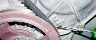
To do this, rotate the engine crankshaft clockwise by the flywheel splines using a large screwdriver until the mark on the camshaft pulley aligns with the mark on the rear timing cover (see photo above).
You can rotate the crankshaft by the bolt securing the generator drive pulley with a key set to “19”. But to access it you will have to remove the right wheel, the right engine protective splash guard, and the generator pulley. The advantage of this additional work will be control over the alignment of the marks on the crankshaft pulley and the marks on the oil pump housing.
We control the alignment of the installation marks
See three photos above.
The mark - the point on the camshaft pulley should be exactly opposite the mark - the protrusion on the rear timing cover.
The mark is a line on the flywheel opposite the middle of the triangular cutout in the degree scale, in the hatch on the clutch housing. Visible if you remove the hatch cover.
And if the mark on the engine crankshaft is checked:
The mark is a point on the crankshaft pulley opposite the mark - a cutout on the ebb of the oil pump housing.
With this arrangement of the timing marks of the 21083 engine, its pistons in the first and fourth cylinders will be at top dead center (TDC). In this case, the first cylinder will have a compression stroke, and the fourth will release exhaust gases.
To install the pistons of the second and third cylinders of the engine at top dead center, rotate the crankshaft clockwise until the mark on the camshaft pulley goes around a full circle - 360 degrees and is opposite the mark on the rear timing cover. In this case, the mark on the flywheel will not be visible; the mark on the crankshaft pulley will also be located opposite the cutout in the ebb of the oil pump housing.
Notes and additions
— What is TDC (top meter point)? TDC is the uppermost position of the piston in the cylinder.
— On some types of oil pumps of the 21083 engine there is no ebb with a cutout, so when setting the marks you need to focus on the pin for installing the generator drive pulley on the camshaft sprocket and the slot in the lower part of the oil pump housing.
Repair work on the engine with installation of the pistons at TDC
Checking the thermal clearances of the valves on the engine 21083 Setting the ignition timing (angle) of VAZ 2108, 2109, 21099 for 92nd gasoline Adjusting the valves of VAZ 2108, 2109, 21099
Installing the piston of the fourth cylinder to the TDC position on a VAZ 2101-VAZ 2107
Many repairs to a car engine involve setting the pistons to top dead center (TDC).
Let's carry out this installation using the example of engine 21083 of VAZ 21083, 21093, 21099 cars.
The mark is a point on the camshaft pulley and the mark is a protrusion on the rear timing cover.
The mark is a point on the crankshaft timing pulley and the mark is a cutout on the oil pump housing.
The mark is a line on the engine flywheel and a mark (triangular cutout) on the degree scale in the clutch housing hatch.
Required Tools
— Large slotted screwdriver
— Key set to “19” or a head with a knob
Preparatory work
— Remove the engine air filter housing
— Remove the protective cover of the timing drive
How to set engine pistons to top dead center (TDC)
- Aligning the factory engine timing marks
To do this, rotate the engine crankshaft clockwise by the flywheel splines using a large screwdriver until the mark on the camshaft pulley aligns with the mark on the rear timing cover (see photo above).
You can rotate the crankshaft by the bolt securing the generator drive pulley with a key set to “19”. But to access it you will have to remove the right wheel, the right engine protective splash guard, and the generator pulley. The advantage of this additional work will be control over the alignment of the marks on the crankshaft pulley and the marks on the oil pump housing.
- We control the alignment of the installation marks
See three photos above.
The mark - the point on the camshaft pulley should be exactly opposite the mark - the protrusion on the rear timing cover.
The mark is a line on the flywheel opposite the middle of the triangular cutout in the degree scale, in the hatch on the clutch housing. Visible if you remove the hatch cover.
The mark is a point on the crankshaft pulley opposite the mark - a cutout on the ebb of the oil pump housing.
With this arrangement of the timing marks of the 21083 engine, its pistons in the first and fourth cylinders will be at top dead center (TDC). In this case, the first cylinder will have a compression stroke, and the fourth will release exhaust gases.
To install the pistons of the second and third cylinders of the engine at top dead center, rotate the crankshaft clockwise until the mark on the camshaft pulley goes around a full circle - 360 degrees and is opposite the mark on the rear timing cover. In this case, the mark on the flywheel will not be visible; the mark on the crankshaft pulley will also be located opposite the cutout in the ebb of the oil pump housing.
Notes and additions
— What is TDC (top meter point)? TDC is the uppermost position of the piston in the cylinder.
— On some types of oil pumps of the 21083 engine there is no ebb with a cutout, so when setting the marks you need to focus on the pin for installing the generator drive pulley on the camshaft sprocket and the slot in the lower part of the oil pump housing.
Repair work on the engine with installation of pistons at TDC
Welcome! First, let’s look at the meaning of the abbreviation “TDC” - “Top Dead Center”. Below we will consider its display on cars of the classic family.
Note!You will need to have a special wrench to turn the crankshaft pulley. If this is not available, use a 36mm socket.
Before starting work that requires removing the timing chain from the vehicle. Usually, after this, the valve timing is disrupted, and you will most likely encounter unstable operation of the car engine. Therefore, before proceeding with such a procedure, it is necessary to set the piston of the fourth cylinder to the TDC position.
Top dead center (TDC) for piston No. 1 - installation
1 The movement of the piston from the lower to the upper position is called the stroke of the piston. Top dead center is the point of highest position occupied by the piston when the crankshaft rotates. Since the piston reaches its highest position twice during the working cycle (once at the end of the compression stroke and again at the end of the exhaust stroke), TDC is usually taken to be the highest position of the piston at the end of the compression stroke.
2 Setting the piston to TDC is the basic procedure for many operations, such as adjusting valve clearance, replacing the timing chain and replacing camshaft/crankshaft sprockets.
3 Before starting this procedure, set the gearshift lever (selector) to neutral and apply the parking brake (or chock the rear wheels). Disable the ignition system by disconnecting the primary circuit connectors from the ignition coil assembly/ignition module (see Chapter 5). Also relieve pressure in the fuel system (see Chapter 4A, paragraph 12).
4 To set any piston to TDC, the crankshaft should be turned clockwise only (as viewed from the timing chain side). This can be done in one of the following ways:
a) Preferred method. The crankshaft is turned with a head with a knob (“ratchet”) using the crankshaft pulley mounting bolt.
b) You can ask an assistant to crank the starter with short turns of the starter (the key is in the ignition switch). To accurately install the crankshaft, you will still need a socket with a crank. Make sure that the assistant has already left the car by this time, removing the ignition key from the lock.
5 Remove the spark plugs and install a compression gauge in the spark plug hole of the first cylinder (see Fig. 3.5)
Rice. 3.5. To determine the TDC of the piston of cylinder No. 1 of the compression stroke, install a compressor in the spark plug hole of cylinder No. 1
(it is preferable to use a device with a threaded tip and a flexible hose about fifteen centimeters long).
6 Rotate the crankshaft clockwise until the gauge needle begins to rise, indicating the compression stroke.
7 After the compression stroke has begun, the piston of cylinder No. 1 must be set to its highest position, which will correspond to its TDC.
8 Continue turning the crankshaft until the mark on the crankshaft damper matches the number “O” (TDC) on the timing cover (see Fig. 3.8).
Rice. 3.8. Align the mark on the crankshaft damper with the o on the scale on the timing chain cover
At this point, the piston of cylinder No. 1 is at TDC on the compression stroke. If the marks coincide, but there is no compression, then this means that the piston is at TDC on the exhaust stroke. Make another full (360°) revolution of the crankshaft.
Note. If a compression gauge is not available, you can insert a blunt object into the No. 1 spark plug hole and then, as the crankshaft rotates, determine the start of the compression stroke by the hissing of the escaping air. The remainder of the procedure is identical to that described above.
9 After piston No. 1 is installed at TDC on the compression stroke, the remaining pistons can be installed in the same position one by one, turning the crankshaft another 180° each time, in accordance with the firing order (see Specifications). For example, by turning the crankshaft 1 80° (from the TDC of the piston of cylinder No. 1), the TDC of the compression stroke will be occupied by the piston of cylinder No. 3.
Watch the video: TDC Top dead center and BDC in an internal combustion engine
How to find VMT without tags
Determining the position of the diesel piston at top dead center
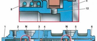
The piston has two characteristic positions: the upper position, when the distance between the piston and the cover is minimal, is called top dead center (TDC), and the lower position, when this distance is maximum, is called bottom dead center (BDC) . The difference between these characteristic points is 180° of crankshaft rotation.
The main piston positions serve as the starting point for all design adjustments of the diesel engine. A device for determining the top dead center is included in the set of tools and accessories for each diesel generator. The degrees of rotation of the crankshaft are counted along the clutch drive disk, which has a graduation from 0 to 360°. Marks are also placed here. m. t. pistons located in the order of operation of the cylinders.
Disc graduation and marking. m.t. are carried out at the factory; In operation, sometimes it is necessary to clarify the correct installation of the arrow from which the position i of the crankshaft is measured. Usually this operation is performed after repairing a diesel engine.
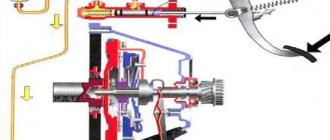
Device for checking c. The m.t. consists of an indicator, a bracket and a rod. The rod is inserted into the cylinder through the indicator channel until it stops at the piston head (the indicator valve must be removed). The movement of the piston when turning the crankshaft is transmitted to the rod and is recorded by an indicator mounted on the bracket.
In order to select the clearances in the camshaft drive, the crankshaft is first turned against the direction of its rotation until the rod of the device moves 3-4 mm, and then in the direction of rotation until the indicator shows 1.5-2. 00 mm (e.g. 1.80 0.02 mm) to zero position. At this moment, the position of the arrow is marked on the clutch disc.
Then the diesel crankshaft is turned in the direction of rotation so that the rod of the device moves 3-4 mm from the zero position (in this case the piston will pass
V. m.t.), and then, choosing gaps, against the direction of rotation so that the arrow of the device indicator does not reach 1.50 - 2.00 m (in this case 1.80 0.02 mm) to the zero position, and mark on clutch disc position arrow. The top dead center is found by halving the distance between the obtained marks on the clutch disk.
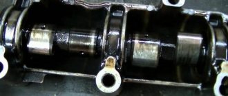
Fixing the piston of the 1st cylinder in the TDC position of the compression stroke
Fixing the piston of the 1st cylinder in the TDC position of the compression stroke
To carry out the procedure for detaching the camshaft drive belt, the piston of the 1st cylinder is fixed in the TDC position so as not to disturb the gas distribution phases, otherwise the engine will function poorly.
Set the TDC of the compression stroke based on the marks of the camshaft wheels. Make sure that the marks match. In case of misalignment, the phase adjustment is disrupted (the piston is not fixed at TDC). Remove the timing belt and rotate the crankshaft until the marks line up.
Useful tips
Due to the difficulty of turning the crankshaft in cars with a manual transmission, you can do the following:
1. Select a gear (we recommend 4th). Drive the car slowly until the marks on the wheels and the rear timing belt cover match.
2. Select a gear. Rotate the front wheel while suspended until the marks coincide.
The TDC marks for the VAZ-21116 and VAZ-11186 engines are located on the protrusion and on the rear cover of the timing belt.
The TDC marks for VAZ-21126 and VAZ-21127 engines are located on the protrusions (A) and on the rear timing belt cover (B).
On vehicles with a manual transmission, the marks are on the flywheel and the scale of the rear clutch guard.
Note
In the images the gearbox has been removed.
Auxiliary marks are applied to the crankshaft wheel and the oil pump cover. These marks can be seen when the generator drive wheel is removed.
To find out whether the marks match or not, do the following.
Take a 17 socket wrench and a 10 socket wrench.
1. Disconnect the wire from the battery (minus terminal)
2. Place shoes under the wheels and place the gear lever in neutral.
3. With the hood open, unscrew the 4 fastening bolts of the upper part of the forward timing cover.
4. Unpin it.
5. Rotate the crankshaft by the fastening bolt until the drive cover marks line up.
6. Remove the plug in the clutch housing and ensure that the marks on the flywheel match.
7. If there is a discrepancy, unfasten the timing belt from the camshaft wheels. Rotate the camshaft until the marks on the rear drive cover and its wheel are in a similar position.
To trace the similarity of the positions of the TDC marks of the VAZ-21126, VAZ-21127 engines, take a 17-point spanner, a 5-point hex key, a TORX T30 wrench and a Phillips screwdriver.
1. Disconnect the wire from the battery (minus terminal)
2. Unfasten the right side of the mudguard.
3. Having opened the hood with a 5-point hex key, unscrew the 5 bolts securing the upper forward timing belt cover.
4. Next, remove the cover.
5. Rotate the crankshaft by the fastening bolt until the marks on the camshaft wheels and on the rear cover match.
6. If the car has a manual transmission, remove the plug (located in the opening of the clutch housing).
7. Observe the similar position of the marks on the flywheel.
Note
In the images, the thermostat has been removed.
8. Observe the position of the wheel marks and the rear drive cover.
9. If the positions of the marks do not match, unfasten the timing belt from the camshaft wheels. Then, rotate the camshafts until the marks on the wheels and rear drive cover are in the same position.
Why is it necessary to set the labels correctly?
The gas distribution mechanism is one of the most important components of a car. The average belt replacement interval is 50-60 thousand kilometers. When replacing it, it is necessary to correctly install the timing marks. All the nuances and features of the process are described in this article. And remember: incorrectly set marks will lead to malfunction of your machine and costly repairs.
For the correct operation of the gas distribution mechanism of a car, it is necessary that the closing and opening of the valves occur in a strictly defined sequence. The slightest inaccuracy in the operation of the camshaft and crankshaft leads to the fact that the gas exchange process in the cylinders is disrupted, and the engine stops working in the correct mode.
A timing belt is a rubber part that during operation can wear out, crack, tear, etc. Therefore, it is necessary to replace the element in a timely manner.
When installing a new one, you should set the labels correctly. This is necessary to ensure that the engine operates correctly from the first seconds of startup. If installed incorrectly, serious problems can occur, including engine failure.
Setting the piston of the first cylinder to the top dead center position
The piston of the 1st cylinder is set to the TDC (top dead center) position of the compression stroke so that when carrying out work related to removing the camshaft drive belt, the valve timing is not disturbed. If the valve timing is incorrect, the engine will not operate normally. In addition, the mark on the camshaft pulley is used to control its position when adjusting the clearances in the valve drive, setting the phase of complete closing of both valves of the 1st cylinder before adjustment.
Set TDC according to the mark on the camshaft pulley (when setting according to the marks on the crankshaft pulley, the piston of either the 1st or 4th cylinder may be in this position). After this, be sure to make sure that the marks on the crankshaft timing gear match (with the auxiliary drive pulley removed). If the marks on the crankshaft pulley do not match, it means that the valve timing is incorrect (the piston of the 1st cylinder is not installed at TDC). In this case, it is necessary to remove the camshaft drive belt and rotate the crankshaft until the marks align.
The crankshaft is turned to check the alignment of the marks on the bolt attaching the auxiliary drive pulley to it, removing the upper part of the right engine mudguard to gain access to it. In addition, you can do this in the following ways (especially when adjusting the clearances in the valve drive, when monitoring by marks on the crankshaft pulley is not needed):
- engage any gear (preferably fourth) and slowly roll the car until the marks align;
- engage any gear and lift one of the front wheels, then turn the suspended wheel until the marks align.
The “a” mark on the camshaft sprocket must be aligned with the “Dacia” logo mark on the cylinder head cover.
... and the mark on the crankshaft timing belt should be aligned with the mark on the cylinder block. It becomes visible after removing the accessory drive pulley. The mark and round protrusion on the toothed pulley must coincide with the hole on the cylinder block.
Tools:
- socket wrenches (heads) to “10”;
- to "18".
- 1. Remove the right front wheel.
- Loosen the wheel bolts only when the vehicle is on the ground. If you are working on an inspection ditch or overpass, place chocks under the wheels, brake the vehicle with the parking brake, and place the front of the vehicle on a secure support.
- 2. Remove the upper part of the right engine splash guard.
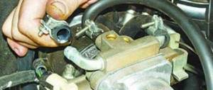
- 3. Remove the accessory drive belt.
4. Remove the right power unit suspension mount.
5. Remove the five bolts securing the upper timing belt cover...
6. ...and remove the cover.
7. Turn the crankshaft clockwise by the bolt securing the auxiliary drive pulley until the marks on the camshaft pulley and the cylinder head cover align. Then loosen the tightening.
8. ... finally unscrew the pulley mounting bolt...
9. ... and remove the pulley.
10. Remove the three bolts securing the lower timing belt cover.
11. ...and remove the cover.
- It is not necessary to first remove the bottom cover when checking the valve timing. This may be required if a phase installation violation is detected and it is necessary to restore the installation by loosening the tension of the timing belt.
12. Check the alignment of the marks on the camshaft timing pulley and the cylinder head cover.
Notes.
* In engines of Dacia Logan/Sandero/Renault Logan, unlike engines of most other car brands, cylinders are counted from the flywheel, and not from the crankshaft pulley.
** In addition to the marks on the pulleys, there are marks painted on the camshaft drive belt, which, when installing the valve timing, must also be aligned with the marks on the pulleys.
Source: https://yourdacia.info/Logan-Sandero/ustanovka-porshnya-VMT.php
Tools needed for work
Installing marks is not an easy process and if done incorrectly, you risk spending a lot of time installing the part. And that's not the worst thing. There are cases when careless drivers break the engine and other mechanisms of the car.
First of all, stock up on the necessary tools:
- Socket head.
- Jack to raise the car.
- Keys No. 17 or 19 - depends on what kind of car you have.
Advice: it is better that you have all key diameters starting from No. 10.
Large flat head screwdriver.
Consequences of incorrect labeling
Before starting work, you need to understand that it is important that during the process of replacing the timing belt, the pre-set risks do not go astray. Otherwise, you will have to go deeper into the settings and spend more than one hour installing the part.
When installing the timing belt, it is important to align the pistons so that in the first cylinder the piston is at the highest point of the first cylinder. In this position, the piston is at its maximum distance from the crankshaft. This is the position the engine is in when the marks are correctly set. In this position it is necessary to change the timing belt.
The number of marks, as well as their location, may vary depending on your engine type.
The following marks can be distinguished:
- Mark on the flywheel.
- Mark on the pulley.
- Camshaft mark (two on a 16 valve engine).
They all must match before replacing the timing belt. In order to set the correct position, rotate the crankshaft by the bolt securing the pulley to it. Please note: turning the camshaft pulley is prohibited.
After you have set TDC, replace the belt and tighten the tensioner.
At the end of the work on installing the belt, rotate the crankshaft several revolutions, check if the marks have gone astray. Repeat the adjustment if necessary.
If the timing marks are set incorrectly, serious consequences for the car can occur.
The most common cases:
- Due to misaligned timing, valves can become deformed during engine operation, and the damage will accumulate.
- The valves will become deformed - bent. Although this will not happen in an 8-valve engine.
- Due to deformation of the valves, the cylinder head may be damaged. As a result, the guide bushings will fail, and cracks may appear on the main power elements.
- The piston mechanism may burn out due to incorrect placement of the timing marks.
- There will be an oil residue on the spark plugs. Plus, the ignition moment of the fuel mixture worsens.
- And also other unpleasant consequences arise.
Labeling
Before starting work, you need to understand that it is important that during the process of replacing the timing belt, the pre-set risks do not go astray. Otherwise, you will have to go deeper into the settings and spend more than one hour installing the part.
When installing the timing belt, it is important to align the pistons so that in the first cylinder the piston is at the highest point of the first cylinder. In this position, the piston is at its maximum distance from the crankshaft. This is the position the engine is in when the marks are correctly set. In this position it is necessary to change the timing belt.
The number of marks, as well as their location, may vary depending on your engine type.
The following marks can be distinguished:
- Mark on the flywheel.
- Mark on the pulley.
- Camshaft mark (two on a 16 valve engine).
They all must match before replacing the timing belt. In order to set the correct position, rotate the crankshaft by the bolt securing the pulley to it. Please note: turning the camshaft pulley is prohibited.
After you have set TDC, replace the belt and tighten the tensioner.