BRAKE SYSTEM
All modern cars have a hydraulic brake system, and discs or drums are used as braking elements. Discs are considered more efficient in their action, but drums do not wear out longer. The brake system of the VAZ 2114 contains the following parts:
- Brake master cylinder;
- Front caliper (right and left, they are not interchangeable with each other);
- Rear brake service cylinder (one for each rear wheel);
- Vacuum booster;
- Tubes;
- Hoses;
- Disks (on the front wheels, identical to each other);
- Drums (on the rear wheels, interchangeable with each other).
From the cabin, the system is controlled using a pedal, the free play is regulated by a rod.
Signs of a faulty brake system
Inattention to the brake system and untimely replacement of consumables lead to unexpected brake failures, so it is always necessary to pay attention to the main signs of a brake system malfunction:
- The braking distance on a dry asphalt surface should be approximately 14 m, and the brake marks should be uniform on all four wheels, and there should be no effect of the car skidding to the side. It is worth noting that the braking distance must correspond to the passport data of the car model, because The data is greatly influenced by the vehicle's curb weight and tire type.
- Increased free play of the brake pedal, which indicates the presence of air pockets in the system or its depressurization. “Getting” of the brakes on the second pump means that there is air in the system, the brake fluid has become unusable, or the working elements of the hydraulic system have worn out. A “soft” pedal on the second or third pitch is guaranteed to indicate a depressurization of the hydraulics. It is unacceptable to continue driving during such manifestations, and towing with a rigid hitch or a tow truck is necessary.
- A “hard” pedal with ineffective braking usually occurs when the brake linings are worn out, the hydraulic system pistons are jammed, or the vacuum booster fails (if the vehicle model has one). It is not recommended to continue driving with such symptoms, and transporting the vehicle is permissible at a reduced speed.
- Ineffective operation of the parking brake only is manifested mainly due to jamming of the mechanism for transmitting force to the brake pads. The aggressive environment of the underbody space rapidly oxidizes and destroys metal, so frequent failures of the parking brake are “sticking” of cables and rods. Another reason is the cable being pulled out, resulting in poor power transmission.
- During long-term high-speed driving and frequent intense braking, periodic manifestations of “sagging” of the pedal appear - the brake fluid boils during braking with the formation of air pockets. This indicates the need to replace it with a new one, with mandatory thorough cleaning of all ventilation holes on the brake discs.
- The car pulling to the side when braking is uneven wear of the brake pads due to jamming of hydraulic system elements or the formation of an air lock in one of the circuits or its depressurization. Repair of the brake system is carried out with the obligatory replacement of all used components and brake fluid, and the replacement of brake pads, discs and drums to ensure uniform production should only be carried out in a comprehensive manner.
- Brake knocking or increased vibration when braking indicates critical wear on the pads, discs and drums. It is necessary to replace worn out parts or restore them. Provided that the braking efficiency is maintained, it is allowed to continue the journey without sudden braking. Emergency braking can cause the pads to jam, causing the wheels to lock.
- Squeaking (creaking) of brakes is a result of poor-quality material on new brake pads or their unacceptable deterioration, leading to metal sliding on metal. Continuation of movement is allowed, because braking efficiency is maintained.
- Jamming of brake pads usually occurs due to corrosion of the metal, so thorough cleaning of the unit with the application of protective reagents is necessary.
REAR BRAKE CYLINDER
The working rear brake cylinder on a VAZ is a device in which two pistons, under pressure created by the liquid, push the rear pads apart. The pads are pressed against the drums and braking occurs.
The rear brake cylinder for 2114 (ZTC) can be of different manufactures. In Russia there are quite a lot of enterprises specializing in the production of spare parts for cars. The original parts are produced by AvtoVAZ; many spare parts for VAZ cars are produced in Samara. But there are also products from other companies (including foreign ones):
- Ate, Germany;
- Samco, Italy;
- Lucas;
- Fenox;
- AP Lockheed;
- "Basalt";
- "Craft".
ZTC Kraft
Among all the listed companies, according to customer reviews, the products of ATE have proven themselves the best. Among Russian brands you can about
Depending on the manufacturer and region of sale, the price of a cylinder on average ranges from 250 to 700 rubles (as of 2105). There is no difference between the VAZ 2114 and VAZ 2115 models; the parts are completely interchangeable with each other.
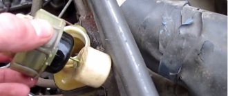
On a fully assembled car, it is not visible where the rear brake cylinder is located; it is located inside the rear drum. But you can understand where it is by looking at the brake pipe that goes to the cylinder.
What is the difference between disc and drum brakes
What is the difference between disc and drum brakes? What's the difference between them?
In today's automobile world, there are two types of brakes - drum type brakes and disc type brakes. Some modern car models are equipped with brake discs on all wheels.
There are also cars in which the front wheels are equipped with disc brakes and the rear wheels are equipped with drum brakes.
To understand the differences between these braking systems, you first need to understand the principle of operation of both.
If you think that the principle of operation of these two completely different types of braking is not much different, then you are mistaken. Both drum and disc brake systems have completely different components.
Brake discs have an open braking system. This system reduces disc rotation due to clamping of the brake pads. The pad and discs are the main elements of the entire system.
The main advantage of this type of braking is that they are open, and this makes it easy to clean from dirt; they cool quickly. The main disadvantage is that the pads wear out quickly.
The reason disc pads will wear out faster is that the force required to press the pad against the disc is many times greater than in drum brake systems.
As you probably already guessed, the main distinguishing feature of a drum braking system from a disc braking system is that the former has operating mechanisms hidden in the inside of the drum.
If, when braking the disc system, the pad is pressed against the disc. In a drum system, it’s the other way around—the shoe expands, as a result of which the drum and, accordingly, the wheels slow down.
The main advantage of this system is its simple design. The main disadvantage is that there is no ventilation.
We will always remain realistic, so we will not hide the fact that disc braking systems are more effective than drum systems.
In general, if you fully understand, the braking system is on discs, and it turned out as a result of the lack of efficiency of their drum counterpart.
This happened because the drum system could not provide the required braking speeds in modern cars.
Of course, the material costs of a disc brake far outweigh a drum brake. One of the main reasons for the difference in investment is that the disc pad will require more frequent replacement.
- Engineers prepare to test Orion splashdown When astronauts return to Earth in the Orion spacecraft, they will have to […]
- Catchable silicone from Daiwa - edible bait Salty Slugger The Daiwa company, specializing in the production of fishing products, never ceases […]
- Best Forex Broker: One for All The fact is that the number of scammers in the Forex market is much less than many […]
- An unknown planet was ejected from the solar system. The solar system probably once had nine planets, but one of them was […]
- Sacred Baikal and its legends On the border strip of the Irkutsk region and Buryatia, a great […]
- Removing an air lock from a car's cooling system An air lock forms in the cooling system. This often happens due to [...]
- Forex Practice Accounts – Is a demo account really useful? Not certainly in that way. Of course, it has its advantages, but it is not without underwater […]
- Plasterboard suspended ceilings Defects often occur in the joints of plasterboard panels. This can be explained [...]
REPLACEMENT
the rear brake cylinders in pairs at once, even if only one of them is leaking . To replace, you will need the following tools:
- Car jack;
- Wheel key;
- Wheel stops;
- Keys for 10 and 12;
- Hammer;
- A wooden block (or better yet, a brass or bronze drift);
- Brake bleeding wrench.
Replacing the rear brake cylinder on a VAZ 2114 occurs as follows (if there is no car lift):
- We loosen the bolts on the rear wheel, lift the car with a jack, and remove the wheel;
- We unscrew the two bolts on the drum (they also serve as guides for the wheel) with a 12mm wrench;
- We remove the drum. If it does not come off, tap it with a hammer through a drift or wooden block. Important! You cannot put the car on the handbrake; the handbrake lever must be fully released;
- Removes the pads;
- Unscrew the brake pipe with a 10mm wrench;
- Unscrew the two cylinder mounting bolts (also a 10mm wrench).
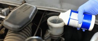
That's it, rear brake cylinder 2114 has been removed. One more small nuance. When we disconnected the tube from it, liquid began to flow.
It’s better to plug the pipe with a wooden tip - less fluid will have to be filled, and it will be easier to bleed the brakes.
Installing the rear brake cylinder is done in the reverse order.
That's all, we've figured out how to replace the rear brake cylinder. You should also remove air from the system by bleeding the brakes. After all work has been completed, the functionality of the new part should be checked. Check:
- Is there any fluid leakage after the replacement?
- Are the brake pads spread on the wheel where the brake caliper was changed?
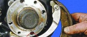
Replacing the rear brake cylinder.
- The first step is to remove the brake drum.
- Raise the handbrake all the way.
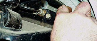
- Remove the cap from the bleeder fitting and use a size 8 wrench to completely unscrew it.
- Lubricate the fitting with grease.
- Loosen the brake pipe fitting.
- We finally unscrew the fitting.
- Unscrew the 2 bolts securing the working cylinder.
- Place the fitting cap on the tube to prevent brake fluid from leaking out.
- Remove the brake cylinder from the shield.
- Before installation, we clean everything from rust and dirt and degrease the working surfaces.
- Reinstall the brake cylinder in reverse order.
- Reinstall the brake drum.
Video on replacing the brake cylinder:
ALWAYS WORKING
There are systems in a car that must always be operational, regardless of age or mileage. Failures of these systems can lead to catastrophic consequences. One of these systems is the brake system. I don’t think it’s worth explaining to anyone that the brake system should always be in perfect order. But it’s one thing when the car is new, and another thing when it’s domestic, and not as new as we would like. Therefore, it is not at all surprising if the braking dynamics deteriorate sharply, and you constantly have to add brake fluid to the reservoir. The reason, most likely, is the failure of one of the five brake cylinders located in your car. To help you find a worthy replacement for a failed unit, we tested VAZ-2105 wheel brake cylinders. Three samples under the trademarks Nobel, Allied Nippon and Fenox were tested. The main objective of our test was to determine the compliance of the presented samples with the requirements of GOST R 52431‑2005 and GOST 23181‑78. Therefore, the following points were included in the test program: 1. Checking the compliance of the connecting and geometric dimensions. 2. Checking the tightness. 3. Durability check during cyclic tests. 4. Disassembly and determination of the condition of parts after the tests.
The only difference from GOST R 52431‑2005 was that we tightened the testing program for checking the working life of the cylinders. The number of cycles was increased from 150,000 (GOST requirements) to 250,000, which approximately corresponds to 4 years of intensive operation. The most interesting thing is that all samples passed tests without any serious complaints and fully comply with the specified GOSTs. We got the impression that they would have lasted 400,000 cycles. When disassembling the samples, it turned out that they all differed from the original products in the design of the adjusting ring and in the type of rubber seal: the original had a torus seal, while the samples had a collar type.
FENOX Classic
ALLIED NIPPON
NOBEL
The Nobel wheel cylinder did not let down its colleagues in the test and passed life tests without serious complaints. The stumbling block was again the adjustment ring. For this sample, problems arose when checking the pressing force and checking the gap - these parameters went beyond the limits of AvtoVAZ requirements.
Despite this, the sample passed the entire cycle of endurance tests without any visible effort. Structurally, the sample differs from the test participants in that the adjusting ring is located after the sealing ring, which means there should be no problems with bleeding the wheel cylinder.
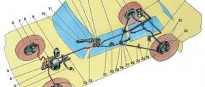
Operating principle of the hydraulic brake system
The hydraulic braking mechanism operates in the following order:
- When the pedal is pressed, mechanical force is transmitted to the GTZ piston.
- When moving inside the master cylinder, the piston creates increased fluid pressure in the hoses (tubes), moving inside which the liquid enters the wheel cylinders.
- The pistons begin to move when the fluid entering the cylinders puts pressure on them. In turn, they act on the pads, as a result of which, depending on the type of system, they move, squeezing on both sides and blocking the brake disc, or move apart, expanding the drum from the inside.
- Brake bars, coming into close contact with the surface of the disc (drum), slow down the movement of the wheel. Thus, the car can reduce speed to the desired limit or come to a complete stop.
1 — brake disc; 2 — front wheel brake caliper; 3 - front contour; 4 — main brake cylinder; 5 — reservoir with a sensor for emergency drop in brake fluid level; 6 — vacuum booster; 7 — pusher; 8 — brake pedal; 9 — brake light switch; 10 — brake pads of the rear wheels; 11 — brake cylinder of the rear wheels; 12 - rear contour; 13 — rear axle axle housing; 14 — load spring; 15 — pressure regulator; 16 — rear cables; 17 — equalizer; 18 — front (central) cable; 19 — parking brake lever; 20 — alarm indicator for emergency drop in brake fluid level; 21 — parking brake warning switch; 22 — brake pads of the front wheels
All this happens when the driver presses the pedal, applying physical force to the brake. When the foot is removed from the pedal, the fluid pressure inside the mechanism is equalized, after which the GTZ piston returns to its place. Return springs, acting on the pads, remove them from the surface of the disc (from the walls of the drum).
The simplest hydraulic drive includes:
- Brake pedal.
- Master cylinder (GTC).
- Wheel cylinders.
- Hoses and tubes.
- Pressure regulator (PR).
- Vacuum booster (not available on all systems).
The GTZ in different machines may differ slightly in design, but the principle of operation is always the same. The brake fluid reservoir is connected to the main line, due to which the following are constantly compensated during operation of the brake mechanism:
- Leakage of liquid composition through cylinder seals.
- Increasing the volume of wheel cylinders when wearing friction linings on the pads.
- Expansion of the fluid as a result of heating.
Brake control loops can be diagonal or parallel, they are separated by a GTZ. Thanks to this scheme, the braking system does not lose its functionality even if one of the circuits fails. This contributes to reliable operation of the mechanism and safe driving.
Pressure regulator
The purpose of this part is to reduce the pressure in the rear wheel cylinders during fast braking. The fact is that when the driver intensively presses the brake pedal, the force of inertia is activated, due to which the mass, and therefore the center of gravity of the car, moves forward, and the wheels located on the rear axle are instantly unloaded. This can cause a skid, and the regulator redistributes the pressure to prevent the rear wheels from losing contact with the road surface.
1 — brake pressure regulator housing; 2 - piston; 3 — protective cap; 4, 8 — retaining rings; 5 — piston sleeve; 6 — piston spring; 7 — body bushing; 9, 22 — support washers; 10 — sealing rings of the pusher; 11 — support plate; 12 — pusher bushing spring; 13 — sealing ring of the valve seat; 14 — valve seat; 15 - sealing gasket; 16 - plug; 17 — valve spring; 18 - valve; 19 — pusher bushing; 20 — pusher; 21 — piston head seal; 23 — piston rod seal; 24 - plug; A, D - chambers connected to the main cylinder; B, C - chambers connected to the wheel cylinders of the rear brakes; K, M, N - gaps; E - drainage hole
Vacuum brake booster (VUT)
This element is responsible for increasing the pressure of the working fluid in the braking mechanism. As a rule, it is included in a common module with the GTZ. The VUT includes a circular chamber, which is internally divided into 2 parts by means of an elastic diaphragm. One of the parts of the chamber is connected to the intake manifold of the power unit using a valve. A vacuum is created there, while the second part communicates with the atmosphere. Pressing the pedal increases the pressure, which transfers vacuum to the GTZ piston. As a result, the force with which the braking system bars are pressed against the surface of the disc (drum) increases significantly.
Vacuum amplifier: 1 – tip mounting flange; 2 – rod; 3 – diaphragm return spring; 4 – sealing ring of the master cylinder flange; 5 – main cylinder; 6 – amplifier pin; 7 – amplifier housing; 8 – diaphragm; 9 – amplifier housing cover; 10 – piston; 11 – protective cover of the valve body; 12 – pusher; 13 – pusher return spring; 14 – valve spring; 15 – valve; 16 – rod buffer; 17 – valve body; A – vacuum chamber; B – atmospheric chamber; C, D – channels