What kind of fuel pumps are installed on VAZ 2110/2112 cars
VAZ 2110/2112 cars, depending on the year of manufacture and the type of engine installed, may differ in the method of supplying fuel to the cylinders.
Table: features of fuel supply systems to engine cylinders depending on vehicle modification
| Model/ modification | Year of issue | Engine volume, cm3 | Number of valves, pcs | Injection system |
| VAZ 21100 | 1996–2000 | 1500 | 8 | Carburetor |
| VAZ 21101 | since 2004 | 1600 | 8 | Injection |
| VAZ 21102 | since 2004 | 1500 | 8 | |
| VAZ 21103 | since 2001 | 1500 | 16 | |
| VAZ 21103M | since 2001 | 1500 | 16 | |
| VAZ 21104M | since 2001 | 1600 | 16 | |
| VAZ 21120 | 1999–2008 | 1500 | 16 | Injection |
| VAZ 21121 | 1999–2008 | 1600 | 8 | |
| VAZ 21122 | 1999–2008 | 1500 | 8 | |
| VAZ 21124 | 2004–2008 | 1600 | 16 | |
| VAZ 21128 | 2004–2008 | 1800 | 16 | |
| VAZ 21123 | 1999–2009 | 1600 | 16 |
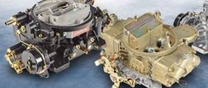
Only the first modifications of the VAZ 2110 were equipped with a carburetor injection system. From the factory they were equipped with mechanical fuel pumps of the DAAZ brand (catalog number 2108–1106010). Previously, they had proven themselves well on cars of the Sputnik and Samara series.
A mechanical fuel pump was installed in the engine compartment of the VAZ 2110 to the right of the engine valve cover, and was driven by the camshaft.
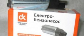
All injection VAZ 2110/2112 are equipped with submersible fuel modules. The design of such a module includes:
- electric fuel pump;
- coarse filter;
- fuel level sensor.
The fuel module is installed directly into the vehicle tank. In other words, the gas pump is completely immersed in gasoline. Injection VAZ 2110/2112 were and are equipped with electric fuel pumps of domestic, joint or imported production. These are products of the Utes, Pekar, Saratov plant, as well as the world famous one, the pumps of which are equipped in all modern VAZs. The catalog number of the stock electric pump is 2112–1139009. There are also modifications whose numbers have two additional digits: 02 or 03. Depending on them, products may differ in length and diameter.
Schemes 2110, 2111, 2112 — DRIVE2
The first 2110 has minor changes. For example, the fuses for the rear fog lights and central locking may not be in the mounting block, but next to it. I did not find such schemes.
The VAZ-2110 was produced at AvtoVAZ from 1995 to 2007, in Ukraine from 2007 to 2014. The VAZ-2111 was produced at AvtoVAZ from 1998 to 2009, in Ukraine from 2009 to 2014. The VAZ-2112 was produced at AvtoVAZ from 1999 to 2008 (2002-2009 the 21123 coupe was produced).
About the mounting block here www.drive2.ru/b/1728977/ About devices here www.drive2.ru/b/1142904/
Diagrams of cars with instrument panel 2112
www.drive2.ru/b/937838/ Several harnesses have been replaced, the rest is the same as on conventional panels.
Carburetor diagram 2110
content-10.foto.my.mail.r…hofer2107/3817/b-4355.jpg ZPTF button with fixation. The result is a diagram of cars produced approximately before 2000.
Scheme 21102 with injector January-4
content-28.foto.my.mail.r…hofer2107/3817/b-4352.jpg The same injection.
Scheme 21102 with injector January-5.1
content-18.foto.my.mail.r…hofer2107/3817/b-4353.jpg The same 16 valve.
______________________________________________________________________________________________ Individual schemes 2110, 11, 12 editions after approximately 2000.
- Front harness diagram
content-10.foto.my.mail.r…hofer2107/3817/b-4350.jpg Connects only to the instrument panel harness.
-Instrument panel harness diagram
content-10.foto.my.mail.r…hofer2107/3817/b-4354.jpg ZPTF button without fixation. The injector connector is 14-pin.
-Diagram of the air supply and heater box harnesses
content-3.foto.my.mail.ru…hofer2107/3817/b-4347.jpg Front wiper, heater. They are connected together with the instrument panel.
-2110 Rear Harness Diagram
content-5.foto.my.mail.ru…hofer2107/3817/b-4343.jpg For the lights, trunk lid and license plate lights. They are connected together and the light harness is connected to the instrument panel harness. The connector with the white wire of the trunk lid harness is connected to any harness of the side doors, from it to any additional harness (will be lower) with the trunk opening button. The connector with the gray wire of the light harness is connected to the instrument panel; on luxury versions it is connected to the instrument panel through the luxury side door harness (where the heated mirrors are connected to it).
-2111 Rear Harness Diagram
content-18.foto.my.mail.r…hofer2107/3817/b-4357.jpg For the lights and rear door with license plate illumination. They are connected together and the light harness is connected to the instrument panel harness and any side door harness, from it with any additional harness (will be lower) with the trunk opening button. The connector with the gray wire of the light harness is connected to the instrument panel; on luxury versions it is connected to the instrument panel through the luxury side door harness (where the heated mirrors are connected to it).
- Rear Harness Diagram 2112
content-13.foto.my.mail.r…hofer2107/3817/b-4358.jpg For the lights, rear door and license plate lights. They are connected together and the light harness is connected to the instrument panel harness and any side door harness, from it with any additional harness (will be lower) with the trunk opening button. The connector with the gray wire of the light harness is connected to the instrument panel; on luxury versions it is connected to the instrument panel through the luxury side door harness (where the heated mirrors are connected to it).
- Harness diagram for additional equipment is normal
content-25.foto.my.mail.r…hofer2107/3817/b-4341.jpg Power window relay and trunk release button. Connects to the instrument panel harness, mounting block and to the regular side door harness.
-Diagram of the additional luxury equipment harness and PTF harness
content-9.foto.my.mail.ru…hofer2107/3817/b-4342.jpg Power window relay, seat heating relay, light button relay and the PTF itself, as well as the trunk lock release button. They are connected together and the additional harness is connected to the instrument panel harness, the mounting block and to any side door harness.
-Side door wiring harness diagram standard
content-10.foto.my.mail.r…hofer2107/3817/b-4349.jpg Central locking and esp.
-Diagram of the side door harness for the luxury package and the front door harness
content-20.foto.my.mail.r…hofer2107/3817/b-4348.jpg Central locking, ESP, electric drive and heated mirrors, wiring from the radio to the speakers.
-Heated seat harness diagram
content-25.foto.my.mail.r…hofer2107/3817/b-4346.jpg It is connected only to the side door harness of the deluxe configuration, and the additional harness must also be deluxe (with fog lights). ______________________________________________________________________________________________
ATTENTION!
The cars differ slightly in how the heater is connected. Therefore maybe
www.drive2.ru
Design features of fuel pumps for carburetor and injection fuel injection systems
Mechanical fuel pumps, which were installed on the first modifications of the VAZ 2110/2112, have a simple design. It is based on a set of membranes made of special rubberized fabric that is resistant to the chemical action of gasoline. The pump body has two valves: inlet and outlet. The membranes are driven by a rod (pusher). It is driven by a cam mechanism rotated by a camshaft.
Such a mechanical fuel pump can serve for decades until the drive rod wears out or one of the membranes breaks. And even then, if this happens, you can replace these elements in half an hour.
The first modifications of the VAZ 2110 with a carburetor injection system were equipped with mechanical fuel pumps
With an electric fuel pump, things are much more complicated. Its design is based on a small electric motor. It is no different from a regular one, although it works completely immersed in gasoline. The pressure in the system here is created not by a membrane (although there are such pumps), but by a specially shaped impeller mounted on the electric motor shaft.
The service life of the electric fuel pump is 150–200 thousand km. But it can fail much earlier. The main cause of breakdowns when the resource is not used up is additives added to gasoline, as well as various kinds of mechanical impurities. The former destroy the brushes and commutator, while the latter clog the valve mechanisms.
In the injection VAZ 2110/2112, the fuel pump has an electrical design and is part of the submersible fuel module
Signs of a faulty fuel pump VAZ 2110/2112
Signs of pump malfunction appear the same, regardless of its design and type of injection system. These include:
- difficulty starting the engine;
- unstable engine operation at idle speed (vibration, tripping, stopping of the power unit);
- failures during acceleration in motion;
- reduction in power and traction qualities of the engine;
- absence of the characteristic sound of a fuel pump starting (for injection engines);
- presence of traces of fuel leakage (for carburetor power units).
Determining a fuel pump malfunction on your own is quite problematic, because the first three signs, which are the main ones, may indicate other problems in the fuel system, such as:
- fuel filter clogged;
- problems with sensors for mass air flow, throttle position, oxygen level, etc.;
- clogging of one or more nozzles;
- failure of the pressure regulator.
In addition, similar symptoms are observed when problems with ignition occur. It can be determined that the cause of the listed symptoms is the fuel filter by checking the device.
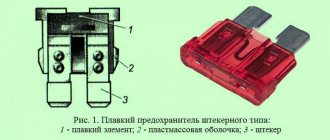
Soulemil › Blog › Diagram and location of fuses VAZ 2110, 2111, 2112
If your windshield wiper blades stop working, or your turn signals stop turning on, do not run to buy a wiper motor or new light bulbs. Most often the problem is burnt fuses. The operation of all electrical appliances in the car is ensured by fuses. It is thanks to them that when a short circuit occurs, all the wiring does not burn out. Let's look at the fuse diagram for the VAZ 2110, 2111, 2112.
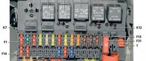
First of all, let's mark all the fuses with their numbers:
Explanation of fuse values: Fuse No.: Amps Responsible for: F1 5 Lighting lamps: numbers, instruments, dimensions on the dashboard, left dimensions, trunk light F2 7.5 Low beam in the left headlight F3 10 High beam in the left headlight F4 10 Right front fog lamp F5 30 Door windows F6 15 Portable lamp, cigarette lighter F7 20 Radiator fan, horn F8 20 Heated rear window F9 20 Windshield washer and wiper F10 20 Reserve F11 5 Clearance on the right side F12 7.5 Low beam in the right headlight F13 10 High beam in the right headlight F14 10 Fog lamp, left F15 20 Heated seats F16 10 Hazard signal, turn signals F17 7.5 Brake light, ignition switch illumination, interior lighting F18 25 Cigarette lighter, glove compartment light, interior heater F19 10 Reversing lamp , monitoring the serviceability of the brake light F20 7.5 Rear fog lights Additional fuses and relays are located to the right of the center panel. Unscrew the screws and remove the cover:
Next we see these fuses:
1 - ignition module 2 - speed, air flow, heating sensors 3 - fuel relays, pump, injectors 4 - fan 5 - fuel pump 6 - ignition Now you know how to change fuses on your VAZ 2110, 2111, 2112 yourself. The procedure is quick and simple.
I brought this out for myself so that I could quickly log into the blog and see which fuse is responsible for what for other users. Thank you!
52 likes Subscribe
How to Test a Mechanical Fuel Pump
To check a mechanical fuel pump, you will need the following tools and tools:
- screwdriver with Phillips bit;
- slotted screwdriver;
- key (head) 10;
- key to 13;
- 2 clean dry plastic bottles with a volume of 2 liters;
- a piece of hose (50 cm) of the same diameter as the fuel one;
- 1–1.5 liters of gasoline;
- caliper (ruler);
- stopwatch (clock).
Let's start with performance. A working VAZ 2110 mechanical fuel pump with a obviously clean filter should pump at least 1 liter of fuel per minute. The verification algorithm is as follows:
- We lift the hood and find the pump.
- Using a screwdriver, unscrew the screw of the pump outlet hose clamp. Loosen the clamp and remove the hose from the pump fitting.
A performance test involves measuring the amount of fuel pumped over a specified period of time.
If the amount of fuel pumped in 1 minute is less than 1 liter, the fuel pump is faulty
If the amount of fuel pumped per minute is less than a liter, the pump is faulty. The reasons for this may be:
- faulty valves;
- rupture of one or more membranes;
- clogging of the pump grid;
- wear of the drive rod (pusher).
We carry out further checks in the following order:
- Disconnect both fuel line hoses from the pump.
Disconnect the inlet and outlet hoses
When you press the manual pumping lever, you should feel a vacuum at the inlet fitting, and a pressure of air at the outlet
The mesh filter should not show signs of damage or deformation
Unscrew the two nuts and remove the fuel pump from the studs.
To disassemble the pump you need to unscrew 6 screws around the circumference of the housing.
The length of the pusher should be 82.4 mm
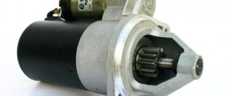
Checking the electrical circuit
Unlike a carburetor engine, where the fuel pump is mechanically driven, on the injection VAZ 2110/2112 a special relay and fuse are responsible for the operation of this device. Therefore, before moving on to diagnosing the pump itself, it is necessary to check the indicated elements. If any one of them is faulty, the pump will not work at all.
Turn on the ignition without starting the engine and listen. When the fuel pump is running, it emits a characteristic “whistle” when started. If it is not there, it means that either the pump itself has failed, or one of the elements of its power supply circuit has failed.
The pump relay and fuse are located in an additional mounting block located inside the vehicle's center console. It can be accessed by removing the plastic trim (near the front passenger's left foot). It is secured with several screws. Under the cover you will find three relays and three fuses. Typically, the fuel pump circuit protection elements are located centrally.
The relay and fuse are located in an additional mounting block under the cladding
To check the fuse, remove it from its socket and “ring” it with a tester. If necessary, replace it, observing the rating (15 A). It is unlikely that it will be possible to check the relay for functionality without special equipment. But you can take another relay, for example, the radiator fan (far left), and install it in place of the one being diagnosed. Turn on the ignition and listen to see if the fuel pump starts working. If yes, buy and install a new relay. If the problem persists, continue diagnostics.
To check the fuel pump relay, you can install the radiator cooling fan relay in its place.
Principle of operation
VAZ 2110 stalls, the fuel pump relay clicks
The operating principle is as follows:
- the relay uses a classic contact closure circuit;
- the relay core is represented by a classic coil;
- manual supply of the closing and opening signal is also involved.
Today, a modern European car is almost completely automated and the concept of “a car won’t start” is practically not found in economically developed countries. This phenomenon is primarily explained by the automation of the relay operation. In particular, the frequency of contact closure controls the built-in on-board control system, plus the material from which the wiring is made has increased electrically conductive properties. This, in turn, allows for more economical and efficient use of material and technical capabilities:
- Firstly, relay wiring from European manufacturers consists of high-tech alloys, this in turn allows you to avoid such phenomena as wiring burnout as a result of electrical short circuits.
- Secondly, the speed of current conduction is quite high, which ensures almost instantaneous transmission of an electrical impulse from point A to the final conditional point B.
Note. Despite the multiple advantages of relays from European manufacturers, from a practical point of view they are inaccessible to the average motorist. Due to the narrow technical range of compatibility and fairly high price.
Design features of relays from national manufacturers
VAZ 2110 how to check the fuel pump relay
Almost all relays of the national automobile industry are identical to each other, since they are produced according to the general principle, which was developed back in the 70-80s. So, the relay usually consists of 4-5 five terminals. The peculiarity of the structure of a 4-pin relay is the absence of a central terminal. The relay is connected to the electrical network using a special plug made of dense plastic. Inside, this plug contains special openings for wires, which are popularly referred to as “decoys”. Inside the relay itself, there is a coil that is attached to the core.
VAZ 2110 fuel pump switch relay
So:
- When voltage is applied, the core of the electric coil is automatically magnetized, thereby attracting the movable contact to itself, thus closing the electrical contacts, as a result of which a spark is actually formed. The moving contact itself is well fixed in a certain position by a spring. The movement of the contacts depends entirely on the electromagnetic activity of the core.
- Inside the relay there are two moving and two fixed contacts. If the relay has 4 contacts, then it works exclusively for closing; if it has 5 contacts, then it operates in two main modes: closing and opening. Modern relays are equipped with 5 contacts, since in this case, the efficiency and reliability of operation increases significantly.
Note. You should always pay attention to the numbers that are located on the back of the outer surface of the relay, as they indicate which contact is connected to which internal element of the relay. If you connect the plus or minus wire to the wrong contact, then the relay cannot be avoided.
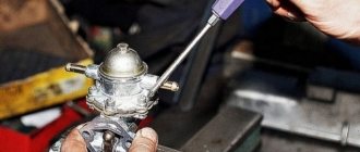
Checking the fuel rail pressure
But even the fact that the fuel pump starts pumping when the ignition is turned on does not mean that it is working properly. The main indicator of its operation is the pressure in the system. You can check it using a regular pressure gauge with a measurement limit of 5–7 atmospheres, which is used to measure tire pressure. In addition, you will need a piece of gas-resistant hose with an internal diameter of 9 mm and two clamps of the appropriate size.
The verification procedure is as follows:
- We relieve the pressure in the system. To do this, disconnect the negative terminal from the battery. We remove the plastic lining of the additional mounting block, which contains the relay and fuse for the gasoline pump. We remove the fuse from the socket. Connect the removed terminal to the battery. We start the engine and let it run until it stalls. After that we put the fuse in place.
- On the fuel rail we find a fitting specially designed for measuring pressure. Using the wheel valve cap, unscrew the spool valve from the fitting.
The fitting is designed specifically for measuring pressure
A regular tire pressure gauge is suitable for measuring fuel pressure in the rail.
For engines with a volume of 1500 cm 3 it should be 2.8–3.2 atmospheres, and for power units with a volume of 1600 cm 3 – 3.6–4 atmospheres. If the device indicators are lower, the pump is unsuitable for further use.
Replacing the fuel pump VAZ 2110 — Lada 2110, 1.5 l., 2004 on DRIVE2
Greetings. I continue my search for sluggish cravings. Before this, perhaps everything that was possible in the fuel system was replaced. Right down to the mesh in the tank. Just recently we adjusted the valves... But that’s not all... The last thing left was the fuel pump. Before a long trip, where I am now, I decided to measure the pump pressure. In the end, not in vain. A worker, everything was as it should be, but he didn’t give out his glasses by an order of magnitude. Those. I could have ridden with him for another 10 years, but maybe I would have died along the way. It was decided to change it and leave the existing one in the trunk as a spare. I bought it on the recommendations of ELCAR. The same Siemens.
Full size
This is such a detail
Full size
According to the diagnostician and the seller, Elcar is nothing more than a Siemens.
The replacement is simple. We remove the pump from the tank and install a new one. There is plenty of information and videos online.
Full size
At the same time, I took a replacement o-ring for the pump body, and 2 rings for the fuel pipes of the tank.
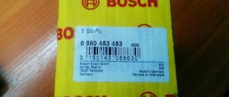
Now for the results. The previously installed Bosch pump, although it was in a dying state, was quieter (from the word “I didn’t even hear it at all”). The new Siemens, when voltage is applied, when the ignition is turned on, creates a louder noise, and during operation, when starting the engine, it is also audible. Barely, but audible if you listen and know all the sounds your car makes. No, of course it’s not critical, but it’s still worth noting. Now for traction. Yes, it has improved a little, it picks up speed a little easier, but again it’s sluggish. Now that everything has already been eliminated by replacing it with a new one, there is only one conclusion. You need to remove the Bosch 1.5.4 ecu and switch to January. If this doesn’t help, then... Then I don’t even know what will... Although on the highway the Bosch brain does not consume fuel, but simply sniffs it. I couldn’t believe my eyes when I walked 569 km. refueled to a full tank (30l.). Consumption was 5.2 liters. At a pace of 90-140 km. Which I consider a good result in terms of efficiency, but I’m not chasing it. I’ll dig further and deeper and make it drive the way a proper 8 bug should drive... PS More for myself. At the same time as replacing the pump, in order to be completely sure of the work done, I washed the throttle again, this time removing it and replacing the gasket.
Full size
Just once
Full size
Pure two
www.drive2.ru
Performance check
Checking its performance will help make sure that the fuel pump has failed. For this you will need:
- screwdriver with Phillips bit;
- a piece of gas-resistant hose (50–80 cm) with a clamp;
- key to 17;
- empty 2 liter plastic bottle;
- a piece of insulated wire;
- stopwatch.
Performance testing is carried out as follows:
- We remove the back seat. We lift the carpet and find the gas tank hatch under it. Unscrew the two screws (diagonally).
- Once you remove the hatch, you will see the top of the fuel module. Using a 17 wrench, unscrew the nut of the outlet fitting. We put a hose on it and secure the connection with a clamp. We lower the other end of the hose into an empty bottle.
- Disconnect the pump power connector. Using a piece of wire, we supply power to the positive contact of the device from the corresponding battery terminal. We connect the negative one to ground.
- We begin counting the time from the moment the pump starts.
A working fuel injection pump for a VAZ 2110/2112 should pump 1.5 liters of fuel in one minute. If this indicator is lower, the pump must be replaced.
Replacing the fuel pump on injection vehicles VAZ 2110/2112
- screwdriver with Phillips bit;
- thin slotted screwdriver;
- key to 17;
- key to 7;
- key to 5.
Procedure for replacing the fuel pump:
- Disconnect the negative terminal from the battery.
- Open the gas tank cap for a few seconds to reduce the pressure inside.
- Remove the rear seat, unscrew the screws, and open the hatch.
Unscrew the two screws securing the protective hatch
Disconnect the electrical connector
Using a 17 wrench, unscrew the nuts of the pump fittings
Using a 7 wrench, unscrew the 8 nuts securing the fuel module flange
Using a screwdriver, unscrew the 2 screws securing the fuel level sensor
Use a screwdriver to remove the clamps on the guides
Using a slotted screwdriver and a 5mm wrench, unscrew the bolts securing the fuel pump cover
We remove the fuel pump from the housing and install a new one in its place.
Having completed the assembly, we check the operation of the new fuel pump.
The process of replacing a VAZ 2110/2112 fuel pump, regardless of its design, does not require any special skills and can be done independently. However, if you are not particularly confident in your own abilities, it is better to contact the nearest car service center.
On any passenger car with a gasoline engine, the gas pump serves to supply fuel under pressure from the fuel tank to the metering device - depending on the modification of the engine on VAZ cars, the fuel system can be carburetor or injection.
The fuel pump (BN) on carburetor internal combustion engines of the 2110 car is located behind the valve cover, next to the distributor-distributor; on a car with an injection engine, it is located in the fuel tank (submersible type). If the BN begins to malfunction, the engine does not pull or develop speed, and in many cases the engine cannot be started at all.
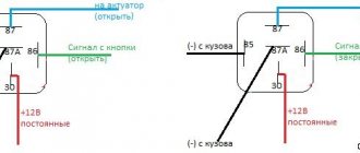
Fuel pump circuit (electric)
The design of the electric fuel pump 2110 itself is quite simple - the unit is an electric motor, which is supplied with 12 Volt power. The BN is mounted in a housing, and a mesh is installed at its inlet - a coarse filter. The filter element prevents dirt particles from penetrating into the pump housing, thereby protecting the device from clogging and possible breakdown.
The electrical circuit of the VAZ fuel pump contains the following elements:
- ignition;
- fuse;
- relay;
- wiring;
- the engine control unit.
When you turn the ignition key, power is supplied through the relay to the BN terminals, and the pump begins to pump gasoline. After the input line of the fuel line is filled with gasoline, the ECU (control unit) through a relay gives a command to turn off the voltage - the fuel system is ready to start the engine, all that remains is to crank the engine with the starter.
Checking the fuel pump relay yourself
At the beginning of the test, you need to get to the following elements: the pump fuse and its relay. Having decided which relay is responsible for the fuel pump, you should also inspect the fuse. Additionally, you need to check the fuse because the fuel pump relay heats up and then does not respond in a timely manner or does not operate at all due to a malfunction of the specified fuse.
Now let's look at another available way to check using the example of a VAZ 2110 car. The fuel pump relay itself in this model is located near the fuse.
- To check, you will need a multimeter or a test light of no more than 0.25 A. Next, you should alternately measure the voltage at the control terminals of the device, simultaneously fixing the contact to ground. This method allows you to accurately determine whether the fuel pump relay needs to be replaced.
- If the warning light does not light up, the pump fuse is working or replaced with a known working one, then attention should be paid to the wiring from the relay to the computer. At the same time, the possibility of malfunctions in the engine control unit should not be ruled out.
Where is the fuel pump relay for VAZ 2110 injector?
Often, due to a relay failure, the engine stops starting; to fix the problem, it is necessary to replace the faulty part. The fuel pump relay (RB) of the VAZ 2110 injector is located in the car interior, under the instrument panel, next to the center console. To get to the pump, you need to unscrew the two screws of the protective plastic casing and dismantle it - of the three elements located here, the “relay” responsible for the operation of the pump will be located in the center (in the figure below, number 5).
Gasoline pump VAZ 2110 injector price
Electric fuel pumps 2110 are produced by various manufacturers; they can be sold either assembled with a housing, or the electric motors themselves can be sold separately. It makes sense to change the BN assembly only when the bulb (body) of the device is damaged; more often than not, only the fuel pump motor itself requires replacement, since it basically stops working.
Main manufacturers of fuel pumps 2110-2112:
For VAZ 2110 injector fuel pumps, the cost may vary; on average, BN can be purchased at a price from 700 to 4500 rubles. The most inexpensive products are produced by Hofer and Pekar; the average price of an electric fuel pump (motor) complete with a Pekar mesh filter is about 800 rubles. The most expensive are Bosch BNs; the cost of the assembled device is 4300-4600 rubles.
Electrical circuit of the fuel pump in the injection VAZ 2110
Fuel pump
Reading time: 3 min.
electrical circuit of the fuel pump VAZ 2110 injector, its structure, principle of operation, as well as methods for checking the main faults in the electrical circuit of the fuel pump.
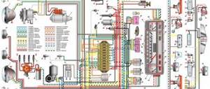
The VAZ 2110 car with an injector system, even several years after the model was discontinued, is still very popular among car enthusiasts. The main reasons for this are the ease of maintenance and reliability of the machine. However, there are also negative aspects: the VAZ 2110 with an injector system very often has problems with electronics. The electrical circuit is quite complex for a Russian car and has 75 elements.
However, the weakest point is the fuel pump.
Its electrical circuit looks like this:
- The main one is the fuel pump relay; all the necessary fuses are installed there.
- Next, the electrical circuit diverges from one of the fuses to the diagnostic block and the device itself.
- From the next to the main relay and injectors.
- Next, the electrical circuit goes to the electronic control unit.
- Also, the fuel pump electrical circuit goes to the battery.
Thus, it turns out that the VAZ 2110 with an injector, the pump contains 4 electrical parts. In case of failures related to the operation of the pump, they should be checked first.
Principle of operation
To make it easier for you to understand the electrical circuit of the 2110 with the injector system, let’s consider its structure and the principle of operation itself.
So, the following take part in the process:
- Electronic control unit.
- Relay for turning on the fuel unit.
- Fuses that protect the electrical circuit of the device from overloads.
Electrical circuit of the VAZ 2110
In practice, the fuel unit starts working the moment the key is turned and ignites one turn. Before starting the engine, listen - at this moment you can hear the device starting to work and pumping gasoline.
Malfunctions in the electrical circuit
Now that you know the structure of the unit, let's figure out what to do if it malfunctions. So, if it shows no signs of life, the problem is most likely in burnt-out electrical parts.
You need to look for them not in the electrical unit, but directly in the interior of the VAZ 2110 with an injector system. The process looks like this:
- First of all, find the fuses. They are located near the front console on the right passenger side. There you need to find the plastic shield and dismantle it. (The part is secured with three self-tapping screws).
- There you will find three fuses and the same number of relays.
- The relay located in the center feeds the fuel. To the left of it is the one that protects the injectors. It must be removed and checked for functionality. If the part is oxidized, clean the contacts. If there is no visible damage, the fuse may have blown and will need to be replaced.
If the above methods do not help, you should not interfere more actively with the electrical system of a VAZ 2110 with an injector system. Unknowingly you can only damage the car.
The fuel unit will stop working and then more expensive repairs will be required. Therefore, it is better to entrust the process to professionals.
autodont.ru
Replacing the fuel pump mesh for VAZ 2110 injector
Russian fuel does not always meet quality requirements, and over time, due to poor gasoline, dirt accumulates in the gas tank in the form of sediment. The debris also clogs the filter screen of the electric fuel pump; due to the accumulated dirt, the fuel does not fully enter the fuel line, causing interruptions in the operation of the internal combustion engine. To eliminate the malfunction, it is necessary to clean or replace the coarse filter, but to get to the mesh, you need to remove the BN.
Before starting disassembly, you should reduce the pressure in the fuel system, otherwise, when unscrewing the fuel line fittings, gasoline may escape in a stream and flood the entire interior of the car. To relieve the pressure, remove the fuse responsible for the operation of the BN, start the engine and wait until it stalls. We replace the VAZ 2110 injector fuel pump mesh as follows:
- turn off the ignition;
- in the back seat in the cabin we find hinges, and by pulling them, we fold the lower “seats” forward (right and left);
- there is a hatch on the bottom under the seat, it is secured with two self-tapping screws;
- unscrew the screws and dismantle the hatch;
- disconnect the plug from the wires that supply power to the electric fuel pump; to do this, bend the latch and forcefully pull the parts of the connector away from each other;
- unscrew the fittings of the fuel pipes - main supply and return (17 mm wrench);
- unscrew the nuts of the pressure plate of the used pump (there are 8 fasteners here, 7 mm wrench);
- The nuts are small, it is better to put them in some kind of jar so as not to lose them. Remove the plate and remove the pump assembly from the gas tank. You need to remove the fuel pump together with the rubber sealing ring and lift the pump carefully so as not to damage the fuel level sensor. When removing the BN housing, it is necessary to tilt it, otherwise it will not come out of the tank;
- remove the screen from the fuel pump and install a new part;
- We install the electric fuel pump in place. Here it is important to put the housing in the old places - if you move the used pump, it will be impossible to tighten the fuel line fittings.
fuel pump — Lada Kalina Sedan, 1.6 l., 2010 on DRIVE2
I came home from work in the evening, parked the car, but in the morning it wouldn’t start, the fuel pump showed no signs of life. No time to figure it out, so I quit until the evening. In the evening I started to tinker: fuse, relay, removed the pump, pulled all the contacts in the module. I connect the power (without installing it into the gas tank) - it gurgles, HURRAY! I install it without a clamping ring, connect it, and it works. I tighten the ring (hammer, flat screwdriver) - it doesn’t work. I pressed the ring - it works. Miracles. After fiddling around for half an hour with “it works or doesn’t work,” I discovered a bad contact in the connector, which is plugged into the b/n module itself. I fixed it in working position, and the next day I bought: Connector with a fuel pump connection wire (pigtail) VAZ 2110, 2111, 2112, 2113, 2114, 2115, Kalina 1117, 1118, 1119, Priora 2170, 2171, 2172, Granta 2190, 2191 , 2192, Niva-Chevrolet 2123, catalog number: 2112-1139080-01, production: Auto VAZ
The sad thing is that you won’t be able to take it and replace it, because... There is no connector in the wiring into which the second end of this cord could be plugged. You'll have to cut into the standard wiring. In general, the fuel pump is a problem, and I have an unpleasant story connected with it: last year my wife and I went to Abkhazia, and on Lake Rizza (high in the mountains), when we were getting ready to leave, it wouldn’t start, the pump wouldn’t pump, there were zero experts nearby (at that time I was still quite green in this matter and there was no Internet at hand either), Kalina in Abkhazia is a wonder. I had to lower it on a tow truck (the ESD and ABS are oak, but there is no way to use a cable). Then I was stuck in Abkhazia for an extra couple of days, and money was running short. What exactly went wrong then - I had neither the desire nor the ability to figure it out, nor the knowledge, so I took public transport all the way to Adler to get a fuel pump assembly (+ bought a relay just in case), changed everything - it started, joy knew no bounds. After that, I removed it a couple more times (apparently there was also a bad contact), and changed the fuel level sensor. Now it seems that I can remove the fuel pump even with my eyes closed. The skill has been upgraded.
www.drive2.ru
Malfunctions of the electric fuel pump 2110
If the pump stops working, there may be several reasons for the malfunction:
- electrical wiring is damaged;
- fuse burned out;
- the relay stopped working;
- BN motor burned out;
- The engine control unit has failed.
When a driver in a car with a VAZ 2110-12 injection engine turns on the ignition, the electric motor starts working - a characteristic buzzing sound is heard. If no sounds are noted, it means that the BN is not pumping fuel.
The easiest way is to check the electric fuel pump fuse, which is located almost in the same place as the relay, located to the left of the RB.
If the fuse is blown, it must be replaced. It often happens that when replacing a fuse, it immediately blows. The main reasons for the malfunction of this phenomenon:
- the fuel pump itself “shorts”;
- There is a short circuit in the electrical wiring.
Another characteristic malfunction of the electric fuel pump is that fuel is pumped, but the operation is accompanied by loud noise. A noisy fuel pump is a sure sign that this device will not “live” for long and will soon fail.
Soulemil › Blog › Diagram and location of fuses VAZ 2110, 2111, 2112
If your windshield wiper blades stop working, or your turn signals stop turning on, do not run to buy a wiper motor or new light bulbs. Most often the problem is burnt fuses. The operation of all electrical appliances in the car is ensured by fuses. It is thanks to them that when a short circuit occurs, all the wiring does not burn out. Let's look at the fuse diagram for the VAZ 2110, 2111, 2112.
First of all, let's mark all the fuses with their numbers:
Explanation of fuse values: Fuse No.: Amps Responsible for: F1 5 Lighting lamps: numbers, instruments, dimensions on the dashboard, left dimensions, trunk light F2 7.5 Low beam in the left headlight F3 10 High beam in the left headlight F4 10 Right front fog lamp F5 30 Door windows F6 15 Portable lamp, cigarette lighter F7 20 Radiator fan, horn F8 20 Heated rear window F9 20 Windshield washer and wiper F10 20 Reserve F11 5 Clearance on the right side F12 7.5 Low beam in the right headlight F13 10 High beam in the right headlight F14 10 Fog lamp, left F15 20 Heated seats F16 10 Hazard signal, turn signals F17 7.5 Brake light, ignition switch illumination, interior lighting F18 25 Cigarette lighter, glove compartment light, interior heater F19 10 Reversing lamp , monitoring the serviceability of the brake light F20 7.5 Rear fog lights Additional fuses and relays are located to the right of the center panel. Unscrew the screws and remove the cover:
Next we see these fuses:
1 - ignition module 2 - speed, air flow, heating sensors 3 - fuel relays, pump, injectors 4 - fan 5 - fuel pump 6 - ignition Now you know how to change fuses on your VAZ 2110, 2111, 2112 yourself. The procedure is quick and simple.
I brought this out for myself so that I could quickly log into the blog and see which fuse is responsible for what for other users. Thank you!
52 likes Subscribe
How to test a relay
If the electric fuel pump does not show any signs of life when the ignition is turned on, this does not mean that it has burned out. The cause of the malfunction may also be a relay. The easiest way to check the RB by ear is that when you turn on the ignition, the relay should click. If you don’t hear a click, there is a high probability that the “relay” is faulty.
But not everything is so simple - the problem can be “tricky”, for example, the car does not start the first time. The cause of the malfunction may be hidden in burnt relay contacts. It’s quite simple to check the functionality of the pump itself; proceed as follows:
- remove the protective casing, under which there is a block with relays and fuses;
- we unscrew the fastenings of the block, remove it, it remains attached to the wires;
- we pull the RB out of the block, place a jumper between two opposite contacts, thus directly supplying power to the BN;
- If, with such a connection, the electric motor of the pump begins to make noise, it means that the BN itself is working, most likely, the malfunction is hidden in the relay.
If there is no voltage on any of the contacts on the RB block, you should look for a break in the wiring; there may also be poor contact at the place where the wire is attached to the terminal.
Fuel check valve
The electric fuel pump of the VAZ “Ten” has good performance, but it creates too much pressure in the fuel system. In order to bring the pressure back to normal, a VAZ 2110 fuel pump valve is built into the fuel line; it is located in the “outlet” fitting of the BN housing. On the “tens”, a pressure regulator is also installed, which is located behind the fuel rail.
A valve malfunction involves a ball sticking in the open position, and the fuel pressure in the system may drop to zero. If such a problem occurs, the car is very difficult to start, since all the gasoline from the fuel lines goes back into the gas tank when the ignition is turned off. Is it possible to somehow repair the valve?
Drivers of 2110 cars claim that you can try knocking on the fitting in the BN flask so that the shut-off ball falls into place. If the malfunction cannot be eliminated in this way, the electric fuel pump bulb must be replaced, since this housing itself is non-separable.
Mechanical fuel pump malfunctions
All parts of a car engine are subject to wear and aging, and the life of a mechanical fuel pump also depletes over time. Main malfunctions of the mechanical device:
- warping of hulls;
- cracking of the diaphragm;
- valve failures.
If the diaphragm allows air to pass through, the pump may stop pumping gasoline into the carburetor; through the torn diaphragm, fuel enters the crankcase and mixes with the engine oil. When gasoline gets into the oil, fuel consumption increases sharply, and the engine itself starts poorly, especially when warm. Checking the presence of gasoline in the crankcase is quite simple - if you light the oil dipstick with a lighter, a fire will occur, and a gasoline smell will come from the oil crankcase.
A common defect that occurs in mechanical gasoline pumps is warping of the surface at the point where the pump is attached to the body of the auxiliary units. If the surface is deformed, engine oil begins to leak at the joint between the planes.
Fuel pump VAZ 2110 carburetor price
Unlike electric fuel pumps, mechanical fuel pumps are generally cheaper; the price largely depends on the manufacturer. The most famous companies producing gasoline pumps:
The cost of the device ranges from 350 to 850 rubles; repair kits are also sold for used mechanical pumps; the kit contains a diaphragm, rod, and valves. The repair kit is quite cheap - from 70 to 200 rubles, but it does not always make sense to carry out repairs, since the pump assembly itself is inexpensive.
An interesting fact is that the fuel pump for carburetor engines for the VAZ “ten” is suitable for the VAZ 2108-09-099 models, as well as for the Zhiguli VAZ-classic 2101-07. The “Classic” BN differs only in a slightly different arrangement of fuel fittings, and in order to install the pump from the “Classic” on a car 2110, it is necessary to use longer fuel hoses.
Dear customers, in order to avoid errors when sending the fuel level sensor harness 21101-3827010РХ, in the “Comment” line, indicate for which engine power system 21114, 21124 or 11183i, 11194i, your car model, year of manufacture.
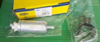
Electric fuel pump assembly - is an electric fuel pump module with a fuel level indicator sensor assembly. Designed to supply fuel from the gas tank to the engine injectors, as well as determine the fuel level and signal its minimum level in the gas tank with an electronic engine control system (ECM)
1- built-in fuel pressure regulator; 2- fittings for installing fuel lines with quick-release tips; 3- electrical connector; 4 — fuel level indicator sensor.
The VAZ 21126 Lada Priora electric fuel pump assembly is of a submersible type, installed in the gas tank located under the bottom of the car body, in the rear seat area behind the service hatch, which, when opened, can be detected.
The submersible fuel pump is lubricated and cooled by fuel.
The fuel level sensor 21101 - 3827010 as part of the fuel system is used to determine the fuel level and is installed directly in the fuel tank. The fuel level sensor is used in conjunction with the fuel level indicator, which in turn is located on the dashboard. The fuel level indicator sensor is based on the operating principle of changing the voltage (pulse height, frequency) at the sensor output when the fuel level in the tank changes.
The fuel level sensor wiring harness 21101-3827010РХ is intended for connection to the common wiring block, as well as to the FLS wiring block from the fuel pump in cars of the VAZ 2110-2112, VAZ 2113-2115, VAZ 2170 family.
Structurally, the fuel supply sensor is nothing more than a rheostat with nichrome resistance. The movement of the movable adjustable contact is carried out through a float lever, the console of which is equipped with an additional contact point. This additional contact, being in a specific position, closes the control circuit, thereby indicating the need to use the fuel volume of the reserve group, which includes a volume from 4 to 6.5 liters. gasoline.
The fuel level sensor is a device of low reliability. Sometimes it becomes necessary to buy a fuel sensor, because after a certain period of operation, the indicators of this device begin to “jump”, that is, produce incorrect parameters. This is due to the fact that the main disadvantage of such a device is the thinning of the track of the contact group under the influence of the friction force of the runner.
In some cases, you can repair the device by slightly bending the so-called. “rocker arm” (bending) of the runner, thereby placing its working contact surface slightly above the wear area of the contact track. If wear exceeds permissible standards, the FLS fuel sensor must be replaced with a new product.
If the fuel tank is half full and the VAZ fuel consumption sensor shows a zero tank fill value, the following measures must be taken:
— test the technical conditions of the contact group on the rear of the instrument panel and, if necessary, tighten the electrical wiring fasteners;
— check the smooth movement of the float spoke, focusing on eliminating unauthorized stops in intermediate positions.
Due to low-quality gasoline and additives, the internal electrical mechanisms in the electric gasoline pump are corroded. When working dry, the brushes overheat and wear out. With proper operation, the service life of the fuel pump is very long.
Connectors DUT 21101-3827010РХ with assembled wiring are highly resistant to adverse environmental influences (high humidity, saline solutions, oil, gasoline and their fumes, aggressive detergents). Connectors with Cargen wires use wires with copper cores with a cross-section from 0.5 mm to 6 mm.
The wiring harness for the fuel level sensor 21101-3827010РХ, fuel pump in cars of the VAZ 2110-2112, VAZ 2113-2115, VAZ 2170 family satisfies the needs of consumers and complies with the requirements of GOST R51814.1-2004 (ISO/TU 16949:2002).
Replacing the wiring harness of the FLS 21101-3827010РХ, located in the electric fuel pump module, connecting the common wiring block, as well as the fuel pump FLS wiring block in cars of the VAZ 2110-2112, VAZ 2113-2115, VAZ 2170 family, can be done independently, without contacting specialized services service.
When replacing a VAZ fuel sensor, it is dismantled along with the electric fuel pump for supplying fuel.
Other article numbers of the product and its analogues in the catalogues: 211013827010 РХ, 211043827010 РХ.
VAZ 2110, VAZ 2112, VAZ 2113-2115, VAZ 2170.
Any breakdown is not the end of the world, but a completely solvable problem!
How to independently replace the fuel level sensor in the VAZ 21126 electric fuel pump on a VAZ family car.
With the online store Discounter AvtoAzbuka, repair costs will be minimal.
Just COMPARE and BE SURE.
Don't forget to share the information you find with your friends and acquaintances, as they may also need it - just click one of the social networking buttons below.
Description for 1st generation
Block on the left side of the dashboard
To gain access, remove the protective cover.
Scheme
Description
A - spare fuses
| 1 | 20A Cigarette lighter |
| 2 | 5A Parking heating (clock, sensor, pump) 15A Circulation pump relay |
| 3 | 20A Additional sockets (12V) |
| 4 | 20A Parking heating - heater |
| 5 | 20A Relay Sockets |
| 6 | 15A KESSY |
| 7 | 5A Diagnostics, multiplex system, rain and light sensor |
| 8 | 30A Windshield wipers |
| 9 | 15A Window washer pump |
| 10 | 25A Window regulator - left rear |
| 11 | 15A Central locking - left |
| 12 | 20A Interior lighting |
| 13 | — |
| 14 | 25A Window regulator - left front |
| 15 | 20A Left rear light |
| 16 | 20A Horn |
| 17 | 10A Turn signal, Parking lights - left |
| 18 | 20A Relay SRA |
| 19 | 15A Fog lights |
| 20 | 30A Electric seats |
| 21 | 15A Additional turning light |
| 22 | 30A Lateral locking, luggage compartment lid control unit 2 |
| 23 | 10A Cross-locking at rear |
| 24 | 5A Tire pressure monitoring system |
| 25 | 15A Steering column adjustment - electric |
| 26 | 10A Airbag control unit, Front passenger airbag deactivation, clutch pedal switch |
| 27 | 5A Switch for disabling the interior security system, interior lighting |
| 28-32 | Reserve |
| 33 | 15A Steering wheel heating, steering column control unit |
| 34 | 5A Heated seat sensor, Interior security surveillance |
| 35 | 15A Low beam, High beam 30A On-board power supply control unit |
| 36 | 10A Powered by on-board battery |
| 37 | — |
| 38 | 10A Brake lights |
| 39 | 5A Relay for ignition system, air conditioning system, heated seats, instrument panel |
| 40 | 5A Instrument panel |
| 41 | 15A KESSY |
| 42 | 30A Electric sunroof |
| 43 | 30A Subwoofer |
| 44 | 30A Electric seat devices |
| 45 | 30A Electric seat devices |
| 46 | — |
| 47 | 10A Cross-axle differential lock control unit |
| 48 | 5A Parking heating clock, lane change assist control unit |
| 49 | 5A Servotronic |
| 50 | 10A Oil level and temperature sensor, Heater pipe blower (VR6) |
| 51 | 5A Air quality sensor, Tire pressure monitoring system, Diagnostics |
| 52 | 30A Rear wiper |
| 53 | 5A Security surveillance of the interior, External lighting switching unit, Heated mirrors |
| 54 | 10A Headlight range control |
| 55 | 15A supply fan relay (speed 2) |
| 56 | 40A Air conditioning system |
| 57 | 40A Bitron fan control motor |
The cigarette lighters are controlled by fuses numbered 1, 3 and 5 at 20A.
Fuse No. 1 is: cigarette lighter + 12v socket in the central tunnel for rear passengers. Fuse No. 3 is: a 12v socket in the luggage compartment (in the wall on the right), the one closer to the fifth door. Fuse No. 5 is: a 12v driver's socket (at the automatic transmission handle) and a 12v socket in the luggage compartment (in the wall on the right).
Block on the right side of the dashboard
Located at the right end of the dashboard, also covered with a protective cover.
Scheme
Designation
| 1 | 15A trailer recognition control unit |
| 2 | 5A Parktronic, Compass |
| 3 | 15A Trailer control unit |
| 4 | 5A Telephone |
| 5 | 15A Trailer recognition control unit |
| 6 | 30A Anti-skid system ESP, ABS |
| 7 | 5A Transfer case control unit |
| 8 | 20A Additional high beam headlights |
| 9 | 5A CD changer |
| 10 | 5A TV tuner |
| 11 | 10A Radio |
| 12 | 30A Audio Amplifier, Antenna Switch |
| 13 | — |
| 14 | 20A Right rear light, 15A trunk lid control unit |
| 15 | 25A Window regulator - right rear |
| 16 | 10A Trunk light |
| 17 | 15A Low beam, High beam |
| 18 | 30A Heated rear window relay |
| 19 | 25/30A Tilt motor for towbar |
| 20 | 30A Electric seat adjustment 20A Inverter with socket, 12V-230V |
| 21 | 10A Security Alarm System, Spare Tire Unlock |
| 22 | 25/30A Electric adjustment of the right front seat, Heated front seats |
| 23 | 10A Air conditioning system |
| 24 | 25/30A Electric seat adjustment |
| 25 | 5A Rear climate control console |
| 26 | — |
| 27 | 15A Tire pressure monitoring system, Level control system control unit |
| 28 | 10A Automatic distance maintenance |
| 29 | 10A Automatic transmission (AT) |
| 30 | 20A Winch, closer relay |
| 31 | 25A Rear control unit, 15A Luggage compartment lid control unit |
| 32 | 10A Central locking - right |
| 33 | 10A Rear alarm system control unit 15A Individual equipment |
| 34 | 25A Window regulator - right front |
| 35 | 10A Turn signal, Parking lights on the right 30A Front passenger seat adjustment control panel |
| 36 | 5A Ceiling module, Telephone |
| 37 | — |
| 38 | EPS, ABS |
| 39 | 10A Air conditioning 5A Windshield heating element relay |
| 40 | 10A Longitudinal interlock |
| 41 | 10A Control unit for trailer |
| 42 | 5A Radio, Garage Door Opener Control |
| 43 | 5A Reversing light switch |
| 44 | Heated windshield washer nozzles, seat heating control |
| 45 | Reserve |
| 46 | Reserve |
| 47 | 10A Automatic distance control, radar sensor, right headlight module |
| 48 | 10A Air suspension control unit |
| 49 | 5A Mirror, Telephone |
| 50 | 5A Parktronic, ASR and ESP shutdown key |
| 51 | 20A Gearbox |
| 52 | 5A Selector |
| 53 | 30A Windshield Heater Relay |
| 54 | 30A Electric trailer brakes, Windshield heating element relay |
| 55 | 20A Electric steering column |
| 56 | 40A ABS, ESP |
| 57 | 40A Longitudinal locking |
Mounting block under the hood
This relay and fuse block is located in the air intake compartment of the engine compartment.
Scheme
Purpose of fuses
| 1 | 60A radiator fan control unit, radiator fan |
| 2 | 30A radiator fan control unit, radiator fan |
| 3 | 40A secondary air pump |
| 4 | 40A secondary air pump |
| 5 | 30A ignition coil, fuses in relay and fuse box |
| 6 | 30A ignition coil |
| 7 | 10A cylinder injectors, fuel cooling pump relay 20A ignition coil |
| 8 | 10A cylinder injector 20A ignition coil |
| 9 | 30A Motronic control unit, engine control unit, diesel injection system control unit |
| 10 | 10A high pressure sensor, air flow meter, air conditioning control unit, generator connection relay, additional cooling system pump relay, brake booster relay (3.2 l), fuel system diagnostic pump, turbocharger control unit |
| 11 | 15A oil level and temperature sensor, Climatronic control unit, absorber solenoid valve, turbocharger control unit 10A air conditioning control unit |
| 12 | 5A secondary air pump relay, electric fuel pump relay 10A absorber solenoid valve 1, regulator, glow plug control unit 20A cooling system thermostat. electronically controlled engine, high pressure sensor, coolant pumping relay after shutdown. engine, climate control unit, intake valve timing control valve, electric motor for changing the geometry of the intake manifold |
| 13 | 15A fuel pressure regulator, fuel pump |
| 14 | 15A fuel pressure regulator, fuel pump 10A fuel metering valve |
| 15 | 15A fuel pump relay, Motronic control unit, engine control unit |
| 16 | 10A battery parallel relay, 30A brake pump |
| 17 | 15A lambda probe 30A lambda probe |
| 18 | 7.5/15A lambda probe after catalyst |
Relay
| A1 | Glow plug control unit (475) |
| A2 | Power supply relay terminals 30 (109) / (219) |
| A4 | Fuel pump relay (53) |
| A6 | Fuel Cooling Pump Relay (404) |
| A5 | Auxiliary Coolant Pump Relay (404) |
| A3 | Control unit for automatic glow plug system (475) |
| B6 | Additional fuel pump relay (449) |
| B7 | Not used |
| B4 | Low power heating relay (100) Power supply relay 1 (100) |
| B3 | High Power Heating Relay (100) |
| B1 | Power supply relay terminal 30 (219) |
| B2 | Fuel pump relay (53) |
| C20 | Power supply relay terminals 50 (433) |
| C19 | Fuel lift pump relay (404) |
Block under the driver's seat
Located on or next to the battery cover.
Scheme
Decoding
- Battery main switch
- Power supply relay terminals 15 (100) / (433)
- Second battery charging relay
| SD1 | 150A Left fuse block |
| SD2 | 150A Right fuse block |
| SD3 | 60A Right fuse block |
| SD4 | 60A Switching block, left fuse block |
| SD5 | 60A Terminal 15 relay |
| SD7 | 250A Parallel connection of battery |
| SD8 | 150A Socket |
| SD9 | 5A On-board power supply control unit |
| SD10 | 10A On-board power supply control unit |
| SD11 | 5A Starter wire diagnostics |
| SD12 | Not used |
| SD13 | 40A Electric motor for ride height control compressor |
| SD14 | Not used |
Relay box under the dashboard
It is located under the front panel on the left.
Scheme
Description
| D1 | Servotronic control unit (476) |
| D2 | Closer relay (404) |
| D3 | Leveling control compressor relay (373) |
| D4 | Socket relay (404) |
| D5 | Air conditioning relay (100) |
| D6 | Fresh air fan relay, speed 2 (404) only with manual air conditioning |
| D7 | Heated rear window relay (53) |
| D8 | Circulation pump relay (404) only VR6 with additional heater |
| D9 | Generator connection relay (53) |
| E1 | Solar disconnect relay (79) |
| E2 | Spare wheel release relay (404) |
| E3 | Heated relay for the left side of the windshield (53) |
| E4 | Circulation pump relay (404) |
| E5 | Relay 2 power supply terminals (432) V10 TDI only |
| E6 | Not used |
| E7 | Headlight cleaning system relay (53) |
| E8 | Residual heat accumulator relay (404) |
| E9 | Heated relay for the right side of the windshield (53) |