Patriot is made mainly according to a single-wire circuit. The negative consumer outputs are connected to the car body and engine, which serve as the second wire. The rated voltage in the vehicle's on-board network is 12 volts. Electrical circuit diagrams for the UAZ-3163 Patriot of different years of production are presented below.
Electrical circuit diagrams for UAZ-3163 Patriot with ZMZ-409 engine produced in 2005, 2007, 2013, 2014.
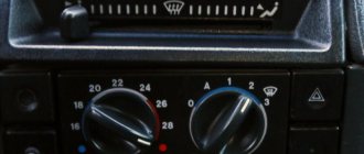
External lighting and fog light switches and an electric fan operating mode switch are located on the console under the instrument panel. The headlight, turn signal, windshield wiper and washer switches are combined into a block of steering column switches. High power electrical consumers are switched on via electromagnetic relays.
The electrical circuits of the engine control system are made according to a multi-wire circuit and are connected to the vehicle ground only through the electronic control unit. To switch the main circuits of the car, a combined ignition switch is used, consisting of a contact part and a mechanical anti-theft device with a lock.
The UAZ-3163 Patriot electrical diagrams have the following wire color designations:
B - white; G - blue; F - yellow; Z - green; K - red; Kch - brown; O - orange; P - pink; C - gray; F - purple; Ch - black; SB - gray with white stripe; SK - gray with a red stripe; SG - gray with a blue stripe; GK - blue with a red stripe; KchB - brown with a white stripe; OG - orange with a white stripe; BG - white with a blue stripe; ZZh - green with a yellow stripe; ZK - green with a red stripe; ZCh - green with a black stripe; RG - pink with a blue stripe; RF - pink with black stripe; FB - purple with a white stripe.
Electrical circuit diagrams for UAZ Patriot with ZMZ-409 engine produced before 2007.
Features of the operation of electrical equipment of the UAZ Patriot.
Any work on electrical equipment should only be carried out with the battery disconnected. — The battery can only be disconnected or connected when the ignition is turned off.
When checking electrical equipment circuits, it is prohibited to short the wires to ground or check the serviceability of the circuits “for a spark,” as this can lead to failure of electrical equipment elements.
It is prohibited to use fuses not provided for by the vehicle design or designed for a higher current, and wire instead of fuses.
When replacing fuses, do not use metal tools, as this may lead to a short circuit in the electrical circuits.
It is prohibited to disconnect the battery while the engine is running to avoid damage to the voltage regulator and elements of the electronic engine control system.
To prevent failure of the diodes of the rectifier unit, it is prohibited to check them on the car with a megger or test lamp, with a supply voltage of more than 12 Volts, without disconnecting the wires from the generator.
You can check the insulation resistance of the generator stator winding with increased voltage only on the generator removed from the car, with the stator winding terminals disconnected from the rectifier unit.
When carrying out electric welding work directly on the car, it is necessary to disconnect the wires from the battery terminals, generator terminals and engine control unit. — It is not advisable to lay low-voltage wires in the same bundle with high-voltage wires.
When recharging the battery using a separate remote device directly on the car, be sure to disconnect the wires from both terminals of the battery.
The Russian SUV Patriot is the flagship of the domestic automotive industry. It is quite reliable, comfortable and has excellent technical characteristics.
Electrical equipment of the car
Domestic SUV
It has 5 doors, which are located in an all-metal body. Serial production of the car began in August 2005 in the city of Ulyanovsk. All-wheel drive and high ground clearance allow you to operate the car on roads with poor surfaces.
The electrical equipment of the UAZ Patriot is made according to a single-wire circuit. The output of each electrical consumer is connected to the positive of the battery, the second wire is supplied to ground. Through it, communication is made with the “minus” of the battery. The ignition key turns on only the main electrical circuit of the UAZ. Electrical consumers such as the cigarette lighter, horn and lamp are turned on without the ignition switch. They are connected directly.
The integrated electrical equipment of the vehicle complies with the Euro-3 standard and is protected by fuses installed in the mounting block. The electrical equipment mounting block can be either domestic or manufactured in Slovenia.
Imported electrical equipment of the UAZ Patriot is inferior to domestic equipment in the sense that it is non-removable and cannot be repaired. If one part fails, the entire board must be replaced. In addition, the following imported components are used in the production of the machine.
- Italian power steering.
- German brake systems.
- Air conditioners made in England.
- Korean seats.
Since the beginning of 2012, production of a car with a domestic turbodiesel engine has been launched. Its environmental safety corresponds to Euro-4 class. A new “Winter Package” option has been added to the car. It includes heated rear seats, heated front glass, and a separate heater for heating rear passengers.
Wiring diagram UAZ Patriot after 2007 (Euro 3)
After 2007, due to stricter requirements for environmental standards, the electrical circuit of the UAZ Patriot was changed and improved. A new electrical circuit has been implemented for connection to an engine according to the EURO 3 standard.
To display the picture in full size, click on it and the electrical diagram will open in a new window.
Name of components and elements used in the electrical circuit of UAZ Patriot after 2007 (EURO 3)
1, 8 — headlights; 2, 3 — fog lights; 4, 5 — sound signals; 6, 7 — electric fans of the engine cooling system; 9 - generator; 10 — rough road sensor; 11 — oxygen concentration sensor; 12-camshaft position sensor (phase sensor); 13-knock sensor; 14 — idle speed regulator; 15,16,17,18 - spark plugs; 19, 20-ignition coils; 21 - crankshaft position sensor; 22, 23, 24, 25 fuel injectors; 26 — throttle position sensor; 27 — mass air flow sensor; 28 — warning lamp sensor for emergency drop in oil pressure; 29 — oil pressure indicator sensor; 30, 31 — coolant temperature sensor; 32 — adsorber solenoid valve; 33 — warning lamp sensor for emergency overheating of the coolant; 34, 35 — pumps for windshield and tailgate glass washers; 36 — rear left speed sensor; 37 — rear right speed sensor; 38 - front right speed sensor; 39 — front left speed sensor; 40 — control unit for the anti-lock brake system; 41 - battery; 42 — engine control system controller; 43 — diagnostic block; 44 — electric motor of the water pump; 45 — heater fan electric motor; 46 — windshield wiper gearmotor; 47 — starter; 48 — brake system emergency warning lamp switch; 49 — relay for turning on the tailgate glass washer; 50 - starter relay; 51 — engine control system relay; 52 — electric fuel pump relay; 53 — relay for turning on sound signals; 54, 55 — relay for turning on the electric fan; 56, 57, 58, 59, 60, 61, 62, 63, 64, 65 - pin fuses; 66 — socket for a portable lamp; 67 — left side turn signal; 68 — right side turn signal; 69 — immobilizer; 70 — instrument cluster; 71 — control unit for door lock motors; 72, 73 — lampshades for lighting glove boxes; 74, 75 -magnetic switches for lampshades lighting glove boxes; 76 — mounting block located in the car interior; 77 — lampshade illumination of the mounting block; 78 — right rear view mirror; 79 — additional resistor of the heater fan electric motor; 80, 81 — backlight lamps for the heater control unit; 82 — heater fan motor speed switch; 83 — diagnostic block; 84 — brake light switch; 85 — regulator of the windshield wiper pause duration; 86 — ignition switch (lock); 87 — switch for cleaner and washer of the windshield and tailgate glass; 88 — sound signal switch; 89 — switch for direction indicators and headlights; 90 — lighting control module; 91 — left rear view mirror; 92 — electric window lifter of the right front door; 93 — gear motor of the right front door lock; 94 — fuel level indicator sensor switch; 95 — switch for additional heater operating modes; 96-additional interior heater; 97 — acceleration sensor; 98 - parking brake warning lamp switch; 99 — cigarette lighter; 100 — alarm switch; 101 — switch for heating the glass of the tailgate and rear-view mirrors; 102- left front door lock motor; 103-electric window lifter of the left front door; 104 — gear motor of the right rear door lock; 105- reverse light switch; 106 — switch for the transmission operating mode warning lamp; 107 — speed sensor; 108 — electric fuel pump with fuel level sensor of the right tank; 109 — right front door power window switch; 110 — control panel for exterior rear-view mirrors; 111 — left front door power window switch; 112-left tank fuel level indicator sensor; 113 — gear motor of the left rear door lock; 114 — light switch on the tailgate pillar; 115,116 - lighting switches on the right door pillars; 117 — rear interior lamp; 118 - front interior lamp; 119,120 - directional lamps; 121,122 - lighting switches on the left door pillars; 123 - light on the right rear fender; 124-element of the rear door glass heater; 125-additional brake light; 126 — rear door glass wiper motor; 127,128 - license plate lights; 129 — rear door lock motor; 130-light on the left rear fender
Electrical wiring location
All electrical wiring of the car is made in the form of cable harnesses that diverge from the mounting block to the corresponding components. The connection of wires to auxiliary relays, the instrument panel and other elements of electrical equipment occurs through the fuse block. Domestic mounting blocks can be disassembled. Thanks to this, the UAZ electrical circuit can be easily restored after a breakdown. To do this, it will be enough to identify the burnt part in the printed circuit board and replace it.
Auto electronics
So that the driver can understand the principles of operation of electrical equipment, the technical description of the machine contains detailed drawings and descriptions of the operation of the most important components and mechanisms. If the electrical circuit in some board has damage to the current-carrying path, soldering a thin wire in this place is allowed. In this case, the malfunction will be eliminated with virtually no material costs.
Detailed diagrams make it possible to imagine the operating principle of electrical equipment. In this case, the UAZ diagram looks like this: Fig. 1.
During vehicle maintenance, the coolant level, lubrication system, amount of brake fluid in the brake cylinder reservoir and tire pressure are checked.
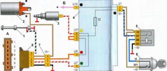
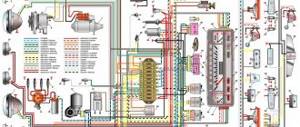
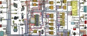
Diagram 1. Connections of the engine control system mod. ZMZ-409 (Euro-2) Scheme 2. Electrical equipment of UAZ Patriot vehicles produced before 2007. Scheme 3. Electrical equipment of UAZ Patriot vehicles produced since 2007. Scheme 4. Connection diagram of the mounting block...
1 - battery; 2 — ignition switch (lock); 3, 29 - fuses; 4 — diagnostic block; 5 — electronic engine control unit; 6, 7, 8, 9 — fuel injectors; 10 — idle speed regulator; 11, 12 — ignition coils; 13, 14, 15, 16 — spark plugs; 17 — instrument cluster; 18 — tachometer; 19 — signal lamp; 20 — air temperature sensor in the inlet...
1, 2 — headlights; 3, 4 — fog lights; 5, 6 — sound signals; 7 — electric fan of the engine cooling system; 8 - generator; 9 — oxygen concentration sensor; 10 — camshaft position sensor (phase sensor); 11 — knock sensor; 12 — idle speed regulator; 13, 14, 15, 16 — spark plugs; 17, 18 — ignition coils; 19 — crankshaft position sensor; 20, 2…
1, 8 — headlights; 2, 3 — fog lights; 4, 5 — sound signals; 6, 7 — electric fans of the engine cooling system; 9 - generator; 10 — rough road sensor; 11 — oxygen concentration sensor; 12 — camshaft position sensor (phase sensor); 13 — knock sensor; 14 — idle speed regulator; 15, 16, 17, 18 — spark plugs; 19, 20 — ignition coils; 21 - sensor...
The UAZ Patriot SUV has gained wide popularity among the population of the Russian Federation and beyond. After all, the main purpose of the UAZ Patriot SUV is to overcome various kinds of obstacles and operate not only on roads, but also off-road. Due to these indicators, this car must be reliable, comfortable and have excellent technical parameters. Today we will pay attention to the electrical part of the SUV, on which not only the movement of the vehicle, but also its start depends.
Electrical circuit diagrams
Diagram 1. Connections of the engine control system mod. ZMZ-409 (Euro-2): 1 – battery; 2 – ignition switch (lock); 3, 29 – fuses; 4 – diagnostic block; 5 – electronic engine control unit; 6, 7, 8, 9 – fuel injectors; 10 – idle speed regulator; 11, 12 – ignition coils; 13, 14, 15, 16 – spark plugs; 17 – instrument cluster; 18 – tachometer; 19 – “CHECK ENGINE” warning light; 20 – air temperature sensor in the intake pipe; 21 – coolant temperature sensor; 22 – mass air flow sensor; 23 – knock sensor; 24 – throttle position sensor; 25 – camshaft position sensor; 26 – crankshaft position sensor; 27 – fuel pump relay; 28 – main relay of the engine control system; 30 – fuel pump; 31 – ground switch
Diagram 2. Electrical equipment of UAZ Patriot vehicles manufactured before 2007: 1, 2 – headlights; 3, 4 – fog lights; 5, 6 – sound signals; 7 – electric fan of the engine cooling system; 8 – generator; 9 – oxygen concentration sensor; 10 – camshaft position sensor (phase sensor); 11 – knock sensor; 12 – idle speed regulator; 13, 14, 15, 16 – spark plugs; 17, 18 – ignition coils; 19 – crankshaft position sensor; 20, 21, 22, 23 – fuel injectors; 24 – throttle position sensor; 25 – mass air flow sensor; 26 – warning lamp sensor for emergency drop in oil pressure; 27 – oil pressure indicator sensor; 28, 30 – coolant temperature sensor; 29 – air temperature sensor; 31 – adsorber solenoid valve; 32 – warning lamp sensor for emergency overheating of the coolant; 33, 34 – windshield and tailgate glass washer pumps; 35 – diagnostic block; 36 – water pump electric motor; 37 – heater fan electric motor; 38 – starter; 39 – engine compartment lighting lamp; 40 – windshield wiper gearmotor; 41 – brake system emergency warning lamp switch; 42 – electric fan relay; 43 – relay for turning on the tailgate glass washer; 44 – starter relay; 45 – engine control system relay; 46 – electric fuel pump relay; 47 – relay for turning on sound signals; 48, 49, 50, 51, 52, 53 – pin fuses; 54 – battery; 55 – socket for a portable lamp; 56 – left side direction indicator; 57 – right side turn signal; 58 – engine control system controller; 59 – instrument cluster; 60 – control unit for door lock motors; 61, 62 – lampshades for lighting glove boxes; 63, 64 – magnetic switches for glove box lampshades; 65 – relay for switching heater modes; 66 – mounting block located in the car interior; 67 – lampshade illumination of the mounting block; 68 – right rear view mirror; 69 – additional resistor of the heater fan electric motor; 70, 71 – backlight lamps for the heater control unit; 72 – heater fan motor speed switch; 73 – brake light switch; 74 – regulator of the windshield wiper pause duration; 75 – ignition switch (lock); 76 – switch for cleaner and washer of the windshield and rear door glass; 77 – sound signal switch; 78 – switch for direction indicators and headlights; 79 – lighting control module; 80 – left rear view mirror; 81 – electric window lifter of the right front door; 82 – gear motor of the right front door lock; 83 – cigarette lighter; 84 – alarm switch; 85 – switch for heating rear-view mirrors; 86 – heater switch; 87 – switch for additional heater operating modes; 88 – tailgate glass heater switch; 89 – gearmotor of the left front door lock; 90 – electric window lifter of the left front door; 91 – gear motor of the right rear door lock; 92 – reverse light switch; 93 – speed sensor; 94 – electric fuel pump with fuel level sensor of the right tank; 95 – fuel level indicator sensor switch; 96 – right front door power window switch; 97 – control panel for exterior mirrors; 98 – power window switch of the left front door; 99 – additional body heater; 100 – switch for the parking brake warning lamp; 101 – left tank fuel level indicator sensor; 102 – gearmotor of the left rear door lock; 103 – light switch on the tailgate pillar; 104, 105 – light switches on the right door pillars; 106 – rear interior lamp; 107 – front interior lamp; 108, 109 – directional lamps; 110, 111 – light switches on the left door pillars; 112 – lamp on the right rear fender; 113 – rear door glass heater element; 114 – additional brake light; 115 – rear door glass wiper motor; 116, 117 – license plate lights; 118 – rear door lock motor; 119 – lamp on the rear left wing
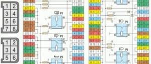
Diagram 3. Electrical equipment of UAZ Patriot vehicles produced since 2007: 1, 8 – headlights; 2, 3 – fog lights; 4, 5 – sound signals; 6, 7 – electric fans of the engine cooling system; 9 – generator; 10 – rough road sensor; 11 – oxygen concentration sensor; 12 – camshaft position sensor (phase sensor); 13 – knock sensor; 14 – idle speed regulator; 15, 16, 17, 18 – spark plugs; 19, 20 – ignition coils; 21 – crankshaft position sensor; 22, 23, 24, 25 – fuel injectors; 26 – throttle position sensor; 27 – mass air flow sensor; 28 – warning lamp sensor for emergency drop in oil pressure; 29 – oil pressure indicator sensor; 30, 31 – coolant temperature sensor; 32 – adsorber solenoid valve; 33 – warning lamp sensor for emergency overheating of the coolant; 34, 35 – windshield and tailgate glass washer pumps; 36 – rear left speed sensor; 37 – rear right speed sensor; 38 – front right speed sensor; 39 – front left speed sensor; 40 – control unit for the anti-lock brake system; 41 – battery; 42 – engine control system controller; 43 – diagnostic block; 44 – water pump electric motor; 45 – heater fan electric motor; 46 – windshield wiper gearmotor; 47 – starter; 48 – brake system emergency warning lamp switch; 49 – relay for turning on the tailgate glass washer; 50 – starter relay; 51 – engine control system relay; 52 – electric fuel pump relay; 53 – relay for turning on sound signals; 54, 55 – electric fan activation relay; 56, 57, 58, 59, 60, 61, 62, 63, 64, 65 – pin fuses; 66 – socket for a portable lamp; 67 – left side direction indicator; 68 – right side turn signal; 69 – immobilizer; 70 – instrument cluster; 71 – control unit for door lock motors; 72, 73 – lampshades for lighting glove boxes; 74, 75 – magnetic switches for glove box lampshades; 76 – mounting block located in the car interior; 77 – lampshade illumination of the mounting block; 78 – right rear view mirror; 79 – additional resistor of the heater fan electric motor; 80, 81 – backlight lamps for the heater control unit; 82 – heater fan motor speed switch; 83 – diagnostic block; 84 – brake light switch; 85 – regulator of the windshield wiper pause duration; 86 – ignition switch (lock); 87 – switch for cleaner and washer of the windshield and tailgate glass; 88 – sound signal switch; 89 – switch for direction indicators and headlights; 90 – lighting control module; 91 – left rear view mirror; 92 – electric window lifter of the right front door; 93 – gearmotor of the right front door lock; 94 – fuel level indicator sensor switch; 95 – switch for additional heater operating modes; 96 – additional interior heater; 97 – acceleration sensor; 98 – switch for the parking brake warning lamp; 99 – cigarette lighter; 100 – alarm switch; 101 – switch for heating the glass of the tailgate and rear-view mirrors; 102 – gearmotor of the left front door lock; 103 – electric window lifter of the left front door; 104 – gearmotor of the right rear door lock; 105 – reverse light switch; 106 – switch for the transmission operating mode warning lamp; 107 – speed sensor; 108 – electric fuel pump with fuel level sensor of the right tank; 109 – right front door power window switch; 110 – control panel for external rear view mirrors; 111 – left front door power window switch; 112 – left tank fuel level indicator sensor; 113 – gearmotor of the left rear door lock; 114 – light switch on the tailgate pillar; 115, 116 – light switches on the right door pillars; 117 – rear interior lamp; 118 – front interior lamp; 119, 120 – directional lamps; 121, 122 – light switches on the left door pillars; 123 – lamp on the right rear fender; 124 – rear door glass heater element; 125 – additional brake light; 126 – rear door glass wiper motor; 127, 128 – license plate lights; 129 – rear door lock motor; 130 – light on the left rear fender
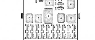
Scheme 4. Connection diagram of the mounting block
Characteristic
The electrical circuit of an SUV is based on a single-wire principle. The positive terminal from the battery is connected to each electrical consumer, and the negative terminal from the battery is screwed to the car body. After turning on the ignition, power is supplied only to the main consumers. All other electrical consumers are powered from the battery directly through the power button.
The electrical equipment of the SUV complies with the Euro-3 standard, and the electrical circuit is equipped with fuses and relays located in the mounting block. For the Ulyanovsk Patriot, the mounting block is mainly manufactured in Slovenia. The peculiarity of such a block from abroad is based on the fact that it cannot be repaired, since it is not dismountable. Therefore, since 2012, the designers of the Ulyanovsk plant began to equip their creations with dismountable mounting blocks.
Helpful information! Since 2012, the Ulyanovsk Automobile Plant has launched the production of diesel engines for the UAZ Patriot SUV. Thus, in 2012, the first SUV of the Patriot model with a turbodiesel engine rolled off the plant assembly line. According to environmental standards and electrical wiring standards, this engine complied with Euro-4 class, which is still a big plus.
Since 2012, the UAZ Patriot SUV has also been equipped with a useful option called “Winter Package”. This package includes the following useful emails: Features:
- heated windshield;
- additional el. a stove that heats the rear of the cabin;
- heated rear seats.
This addition made it possible to make the UAZ Patriot SUV even more comfortable and popular.
Electrical diagram of the equipment of the UAZ Patriot SUV until 2007.
Wiring
Electrical wiring cables are bundles that branch from the mounting blocks and go directly to the equipment. Mandatory elements of a car's electrical circuit are fuses that perform a protective function.
If a breakdown occurs in the mounting block, then domestic models of this product must be repaired. To do this, you need to disassemble the unit and find the fault. Often the malfunction consists of burnt tracks on the printed circuit board. To understand the principle of constructing a printed circuit board, you will need an electrical diagram. This diagram is shown in the photo.
Wiring plays an important role by completing the DC circuit, thereby providing power to each electrical unit. car device.
Electrical diagram of the equipment of the UAZ Patriot SUV from 2007.
Since 2007, manufacturers of domestic SUVs have come to a consensus on the need to switch from the Euro-2 to Euro-3 environmental standard for gasoline engines. As a result of the transition from one standard to another in 2007, the electrical circuit received some modifications. Such an email. The diagram is shown in the figure above, which is a fuel injection system. The electrical circuit of the Patriot from 2007 differs from the circuit of the earlier production of the car in that the system lacked an injection system control unit.
One of the features of modern Russian-made cars is the presence of a large number of various devices and systems that provide more comfortable operation of the cars. UAZ Patriot cars were no exception. What elements does the UAZ Patriot electrical circuit include and how can you identify electrical problems? We will talk about this below.
[Hide]
The most common causes of failure of an electrical part of a car:
- mechanical damage to electrical wiring (open circuit, short circuit, wear of terminals, etc.);
- failure of sensors and components due to moisture ingress and corrosion processes;
- malfunction of control units and control units;
- failure of lighting equipment, fuses, relays;
- malfunctions of electronic components;
- problems with the starter, generator, corrosion of battery terminals.
The UAZ Patriot model range includes cars with engines made according to Euro 2 (before 2007), Euro 3 (produced from 2007 to 2020) and Euro 4 (after 2013) standards. The UAZ Patriot electrical circuit diagram for each modification has its own characteristics associated with the design of the engine control system, the use of various electronic units and other equipment. Thus, cars produced before 2012 were equipped with Slovenian relay and fuse mounting blocks. They have a non-separable design, and theoretically cannot be repaired if they have an internal fault (melted conductors, broken contacts, etc.). In practice, such problems can also be solved, but only by experienced craftsmen and using original methods. Since 2012, Patriot cars have been equipped with a dismountable mounting block of relays and fuses (similar to VAZ), which significantly simplifies the process of repairing this unit. Turbodiesel engines of UAZ Patriot vehicles, which began to be installed on production vehicles in 2012, comply with the Euro 4 standard. Meeting high environmental requirements required the complication of circuit design solutions for electrical equipment of vehicles. The additional equipment of the vehicles includes a “winter package”, which includes the following electrical equipment:
- electric heated windshield;
- additional electric interior heater;
- heated rear seats;
- high capacity battery.
To carry out prompt and high-quality repairs of the vehicle’s electrical equipment, it is necessary to carefully study the electrical circuit diagram corresponding to the year of manufacture of the vehicle.
Peculiarities
The UAZ Patriot electrical circuit consists of many components, its main systems are:
- injection and ignition, including spark plugs, distribution unit, starter;
- generator device and battery;
- motor control device;
- control panel on which sensors and diode indicators are installed;
- steering;
- power windows, if equipped;
- optics;
- lighting in the cabin, as well as the rear license plate of the car;
- an audio system that includes a radio, speakers, as well as an amplifier and subwoofer, if equipped;
- rear window heating unit;
- heating system;
- mounting block with safety elements.
How to determine the malfunction?
How to determine the presence of voltage in a car's electrical wiring:
- To check, you will need a test light; you need to solder two wires to it. One probe of the tester must be connected to the negative terminal of the battery or the car body, and the second to the section of the electrical circuit being tested. In order to more accurately determine the lack of voltage, it is advisable to connect the second probe as close as possible to the battery or fuse.
- If, as a result of connection, the control panel lights up, this may indicate that there is voltage on the device being tested.
- In the same way, you need to check other components of the electrical network. If it happens that the light source does not light up, then the cause of the malfunction must be sought in the area between the point being tested and the last place where the voltage was. Typically, wiring malfunctions are associated with poor contact, so the quality of the connection should be diagnosed. In addition, depending on the section of the circuit being tested, there may be voltage on it only when the key is turned in the lock (video author: Dmitry Sherstnev).
If you have any suspicions about unreliable grounding, you can check it like this:
- First of all, turn off the ignition and disconnect the terminals from the battery. Then, using the same control light, one of its probes should be connected to the Patriot body.
- The second contact from the tester is connected to the grounding point, in particular, we are talking about the area that you are testing.
- If after connecting the light comes on, this indicates that everything is in order with the grounding. Accordingly, you can begin checking other areas.
One of the problems that occurs in the operation of wiring is a violation of integrity, that is, a break or damage to the cable.
To diagnose this problem, do the following:
- First of all, the voltage is disconnected from the electrical circuit; for this, the terminals are disconnected from the battery. Checking the continuity of the circuit is carried out using a test light, as well as a connected power source.
- Then one probe from the testing device must be connected to the positive end of the circuit being tested, the second to ground, that is, the car body. Or two probes from the light bulb are connected to both ends of the area being diagnosed. If the lamp lights up as a result of the connection, this indicates that the circuit is intact and there is no damage in it. Accordingly, if the light does not light up, then the area is damaged.
- The switch is also diagnosed; the tester probes must be connected to the terminals of the device. When the switch is turned on, the lamp should light up.
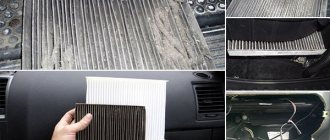
Photo gallery “Main faults”
Possible wiring problems
Problems with the electrical system can be divided into several types:
- Malfunctions of the electrical equipment itself.
- Failure of the safety element. Fuses blow due to natural wear and tear or as a result of voltage surges in the system. If you are faced with a problem where the same fuse repeatedly fails, this may indicate that there is a drop in that section of the circuit. The jump can be due to various reasons, but as a rule, the problem lies in the use of more powerful equipment. For example, if you connect a tee and at the same time power all three sockets of the device, this can lead to a serious surge. Before replacing the fuse, you must make sure that there are no surges in the system.
- Poor contact between the electrical circuit and the equipment. In this case, there may be several reasons. First, you need to check the integrity of the wiring; you already know how to do this. Secondly, you need to check the connection contact itself - there is a possibility that the reason lies in a poor connection, perhaps the contacts need to be changed or cleaned.
- Not so often, Patriot car owners are faced with the problem of current leakage, which, in turn, is usually caused by breakdowns in the electrical circuit. Using a tester or a light bulb, you can determine the failed defective section and replace the damaged cable. If the damage is minor, then several layers of electrical tape can be wrapped around the cable.
- Failure of the generator unit. To determine problems with the generator, you need to remove and disassemble the mechanism to identify damaged components.
- Sometimes car owners are faced with the problem of being unable to start the engine due to a discharged battery. There may be several reasons for the discharge, so in addition to measuring the voltage, you also need to visually inspect the device body and the presence of electrolyte in it. If there is too little liquid in the jars, then its level must be replenished using distillate.